
Fabricated bridge deck structure

A prefabricated, stepped structure technology, applied in the direction of bridges, bridge parts, bridge construction, etc., can solve the problems of difficult control of on-site construction quality, heavy workload of cast-in-place concrete, heavy maintenance and repair workload, etc., to achieve convenient hoisting and prefabrication Installation, fewer construction procedures, less lifting effect

Pending Publication Date: 2019-07-26
CHINA RAILWAY DESIGN GRP CO LTD
View PDF0 Cites 3 Cited by
  • Summary
  • Abstract
  • Description
  • Claims
  • Application Information

AI Technical Summary

Problems solved by technology

The existing auxiliary facilities of the box girder bridge deck have problems such as long construction period, heavy workload of cast-in-place concrete, difficulty in controlling the quality of on-site construction, and heavy maintenance and repair workload during operation.

Method used


Image

  • Fabricated bridge deck structure
  • Fabricated bridge deck structure
  • Fabricated bridge deck structure

Examples


Embodiment 1

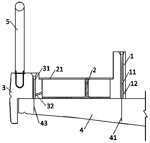
[0050] like figure 1 As shown, the protective wall 1 and the auxiliary foundation 3 are positioned through the prefabricated No. I reserved anchor hole 11 and No. II reserved anchor hole 31 and the No. I connector 41 and No. II connector 43 on the main beam 4, and then pass through the Grouting material is poured into No. 1 grouting hole 12 and No. 2 grouting hole 32 to realize fixed connection.

[0051] The cable duct 2 and the cover plate 21 are placed on the main beam 4 .

Embodiment 2

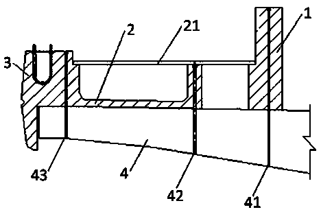
[0053] like figure 2 As shown, the protective wall 1 and the auxiliary foundation 3 are positioned through the prefabricated No. I reserved anchor hole 11 and No. II reserved anchor hole 31 and the No. I connector 41 and No. II connector 43 on the main beam 4, and then pass through the Grouting material is poured into No. 1 grouting hole 12 and No. 2 grouting hole 32 to realize fixed connection.

[0054] The cable duct 2 and the subsidiary foundation 3 are prefabricated together, and a gap is formed between the outer side of the cable duct 2 and the protective wall 1 .

Embodiment 3

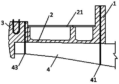
[0056] like image 3 As shown, the protective wall 1 and the auxiliary foundation 3 are positioned through the prefabricated No. I reserved anchor hole 11 and No. II reserved anchor hole 31 and the No. I connector 41 and No. II connector 43 on the main beam 4, and then pass through the Grouting material is poured into No. 1 grouting hole 12 and No. 2 grouting hole 32 to realize fixed connection.

[0057] The cable trough 2 is prefabricated with the protective wall 1 , and the outer side of the cable trough 2 is attached to the auxiliary foundation 3 .


PUM


Abstract

The invention discloses a fabricated bridge deck structure, which includes a protective wall and an auxiliary foundation. The protective wall and the auxiliary foundation are both prefabricated components, a reserved anchor hole I corresponding to a connecting part I on a girder is formed in the protective wall, a reserved anchor hole II corresponding to a connecting part II on the girder is formed in the auxiliary foundation, a cable groove is formed in the girder between the protective wall and the auxiliary foundation, and a cover plate covers the cable groove. According to the fabricated bridge deck structure, modularization, standardization and factory production of the bridge deck structure are realized, site fabricated construction is achieved, the components are flexible in manufacturing, single component prefabrication and combination prefabrication can be achieved, the lifting capacity of the components is small, and lifting and prefabrication and installation are convenient;and ordinary connection components are used, the cost is low, the cable groove is not connected with the girder through the connecting parts, the construction processes are reduced, and the cost is lowered.

Description

technical field [0001] The invention belongs to the field of bridge deck structures, and in particular relates to an assembled bridge deck structure. Background technique [0002] my country's bridges account for a relatively large proportion of the total length of the line, and the main girder is generally a concrete structure. The auxiliary structure of the bridge deck includes protective walls, cable ducts and their covers, shutters, railings (columns and handrails), sound barriers, etc. Generally, protective walls, shutters and vertical walls are all cast-in-place concrete structures. The existing auxiliary facilities of the box girder bridge deck have problems such as long construction period, heavy workload of cast-in-place concrete, difficulty in controlling the quality of on-site construction, and heavy maintenance and repair workload during operation. [0003] On the other hand, my country is currently vigorously developing prefabricated buildings, and the prefabr...

Claims


Application Information

Patent Timeline
IPC IPC(8): E01D19/00E01D19/12
CPCE01D19/00E01D19/12E01D19/125
Inventor 王祯苏伟刘凯冯沛吴长发刘祥君尚海涛饶建雄周维
Owner CHINA RAILWAY DESIGN GRP CO LTD
Learn More