Rock-soil body disintegration test device and analysis method
A technology of testing analysis and testing equipment, which is applied in the field of analysis and testing, can solve the problems of data accuracy error and inability to accurately obtain the disintegration of rock and soil mass, and achieve the effect of improving accuracy and accuracy
- Summary
- Abstract
- Description
- Claims
- Application Information
AI Technical Summary
Problems solved by technology
Method used
Image
Examples
Embodiment 1
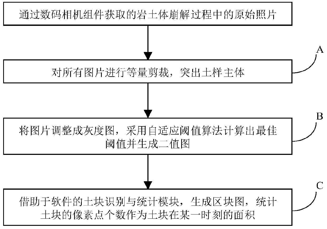
[0060] Such as figure 1 As shown, a rock and soil mass disintegration test device includes a base 10, a support 20, a light box 30, a digital camera 40, an LED light 50, and an open container 60 made of plexiglass; the open container 60 is used to hold Rock and soil samples 70 and deionized water 80 , and a digital camera is connected with an image analysis system 90 . The image analysis system 90 includes a data transmission module, a data processing module, and an image storage module, and the image analysis system 90 is connected to the digital camera 40 in a wireless or wired manner.
[0061] The base 10 is placed on a horizontal desktop, the lighting light box 30 is placed and the LED light 50 is installed and debugged to ensure a stable light flux in the light box and illuminate during the disintegration test.
[0062] The LED lamp 50 is installed on the inner wall of the lighting light box 30, and at least three ring lamp groups are installed to ensure that the rock an...
Embodiment 2
[0076] The installation and analysis methods for the rock and soil disintegration test device are the same as in Example 1, but the rock and soil samples are different. In this embodiment, the sample is a mixture of sand and cohesive soil in Example 1, wherein the average of the sand The particle size is 0.5 mm, and the added mass fraction is 10%. The samples were treated with MICP several times to explore the effect of MICP on the water stability of cohesive soil under different sand contents.
[0077] After 25s disintegration test, the results show that: Figure 5 As shown, the disintegration index of the sample gradually increased with time within 25s and tended to be stable. During the entire disintegration process, the disintegration index increased rapidly in the first 10s, an increase of 0.27 units, indicating that the sample disintegrated violently within 10s. After 10 seconds, the disintegration index gradually stabilized at about 1.32, indicating that the disintegra...
Embodiment 3
[0079] The installation and analysis method for the rock and soil disintegration test device is similar to that of Example 1, but the rock and soil samples are different. In this embodiment, the sample is a mixture of sand and clay, and the average particle size of the sand is 0.5mm. The added mass fraction is 20%. The samples were treated with MICP several times to explore the effect of MICP on the water stability of cohesive soil under different sand contents.
[0080] After 25s disintegration test, the results show that: Figure 5 As shown, the disintegration index of the sample increases gradually with time within 25s, and finally when the disintegration index tends to be stable, it only increases by 0.05 units, which is 15.6% of the sample with 10% sand content. This shows that increasing the sand content by 10% is beneficial to the water stability of MICP modified cohesive soil, and further demonstrates that the disintegration index can effectively characterize the disi...
PUM
| Property | Measurement | Unit |
|---|---|---|
| particle size | aaaaa | aaaaa |
Abstract
Description
Claims
Application Information
 - R&D
- Intellectual Property
- Life Sciences
- Materials
- Tech Scout
- Unparalleled Data Quality
- Higher Quality Content
- 60% Fewer Hallucinations
Browse by: Latest US Patents, China's latest patents, Technical Efficacy Thesaurus, Application Domain, Technology Topic, Popular Technical Reports.
© 2025 PatSnap. All rights reserved.Legal|Privacy policy|Modern Slavery Act Transparency Statement|Sitemap|About US| Contact US: help@patsnap.com


