
Two-step calibration method of light field camera

A technology of light field camera and calibration method, applied in image data processing, instrumentation, calculation, etc., can solve problems such as inability to solve optical parameters, inability to meet usage requirements, etc.

Pending Publication Date: 2019-07-26
英特科利(江苏)医用内窥影像技术有限公司
View PDF0 Cites 8 Cited by
  • Summary
  • Abstract
  • Description
  • Claims
  • Application Information

AI Technical Summary

Problems solved by technology

[0003] The problem to be solved by the present invention is: the existing calibration method for the light field camera is based on the projection model of the light field camera, and can only obtain the projection matrix of the light field camera, but cannot obtain optical parameters with physical meaning, and cannot satisfy Usage requirements

Method used


Image

  • Two-step calibration method of light field camera
  • Two-step calibration method of light field camera
  • Two-step calibration method of light field camera

Examples


Embodiment

[0078] Example: Experiments were carried out with Lytro Illum, a second-generation light field camera produced by Lytro Corporation of the United States. The serial number of the camera is B5152200720. This camera can decode 15×15 sub-aperture images from each light field original image, and each The sub-aperture image resolution is 625×434, the distance between the centers of adjacent microlenses is d=0.01732mm, and the pixel width is q=0.0014mm. A total of 13 angles of calibration plate images are taken. The position optical system between the light field camera and the calibration plate Such as Figure 7 shown. The physical parameters obtained by calibration are shown in the table below:

[0079]

[0080] Figure 8 It is the result of the reprojection error in this embodiment. It can be seen that without nonlinear optimization, the reprojection error is within 0.008mm. After nonlinear optimization, the reprojection error is all within 0.005mm, and most of them are conc...


PUM


Abstract

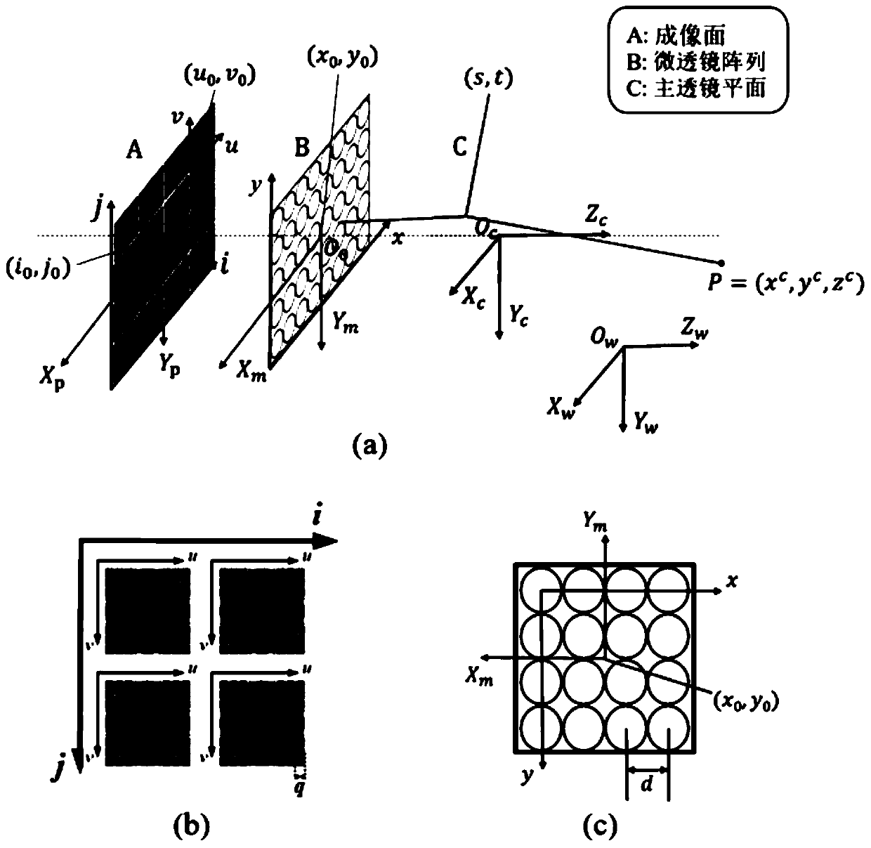
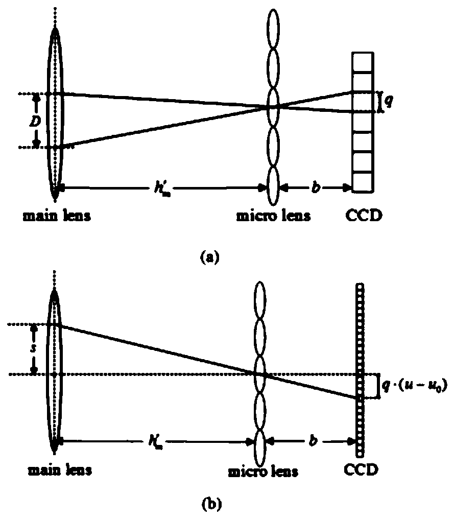
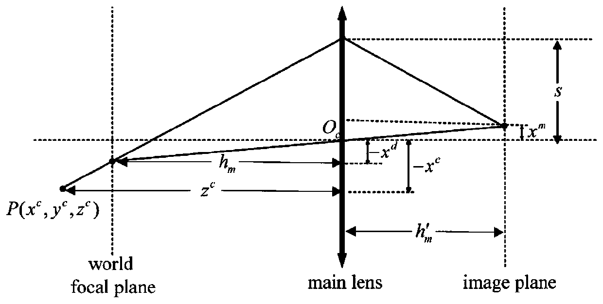
A two-step calibration method for a light field camera is based on a light field camera imaging model, and comprises the following steps: 1, extracting coordinates of feature points in a central sub-aperture image, and calibrating parameters of a main lens by utilizing an equivalent camera projection model; and 2, fitting and solving the parameters of the micro lens by combining the constraint relation between the optical field parallax and the depth of the object, and obtaining the physical parameters of the optical field camera through two-step calibration. Based on the imaging principle ofa light field camera, a projection model capable of being degraded to a traditional camera is established, and particularly, a more universal two-step calibration method is provided for a non-focusinglight field camera. Through derivation of a light field camera imaging model, a central sub-aperture image is equivalent to a traditional camera image, so that a classical Zhengyou plane calibrationmethod is applied to light field camera calibration, and through derivation of a constraint relation between light field parallax and depth, a method of solving microlens parameters through linear fitting is realized.

Description

technical field [0001] The invention relates to camera calibration technology, relates to calibration based on a non-focused light field camera, is used to provide technical parameters for three-dimensional imaging based on a light field camera, and is a two-step calibration method for a light field camera. Background technique [0002] The traditional camera calibration algorithm is based on the pinhole model. First, the image of the calibration plate is taken. The calibration plate is the reference plate whose spatial position of each feature point has been measured in advance, and then according to the projection mapping between the image coordinates of the feature points and the real three-dimensional space coordinates. Relation, solve to get the internal and external parameters of the camera. For the calibration of light field cameras, the current main method is to establish a light field camera projection model different from the traditional model, use the multi-plane ...

Claims


Application Information

Patent Timeline
IPC IPC(8): G06T7/80
CPCG06T7/80
Inventor 周平蔡维嘉于云雷
Owner 英特科利(江苏)医用内窥影像技术有限公司
Learn More