Cut pile reinforcement cage welding device

A technology for welding devices and steel bars, which is applied to welding equipment, auxiliary equipment, auxiliary welding equipment, etc., can solve the problems of vertical steel bar tilting and heavy vertical steel bar weight, and achieve convenient welding operations, low manufacturing costs, and improved welding processing. The effect of quality and welding speed

Active Publication Date: 2021-07-27
MCC5 GROUP SHANGHAI CORPORATION LIMITED
View PDF0 Cites 0 Cited by
  • Summary
  • Abstract
  • Description
  • Claims
  • Application Information

AI Technical Summary

Problems solved by technology

[0003] In view of this, the object of the present invention is to provide a welding device for a pile-cut reinforcement cage to solve the technical problem in the prior art that the vertical reinforcement tends to be inclined during welding due to the heavy weight of the vertical reinforcement when the pile-cut reinforcement cage is welded

Method used


Image

  • Cut pile reinforcement cage welding device
  • Cut pile reinforcement cage welding device
  • Cut pile reinforcement cage welding device

Examples


Embodiment 1

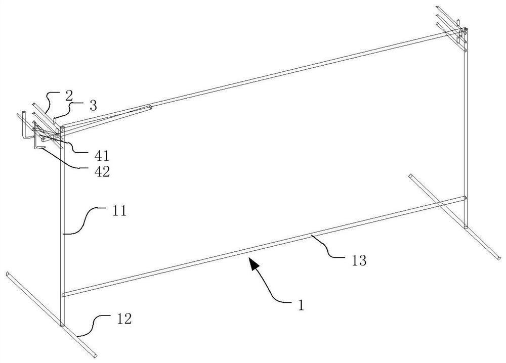
[0025] refer to figure 1 , a pile-cut reinforcement cage welding device is used for welding the pile-cut reinforcement cage. The pile-cut reinforcement cage includes a plurality of vertical reinforcement bars and a supporting plate, and the plurality of vertical reinforcement bars are vertically welded on the supporting plate. This embodiment takes a pile-cut reinforcement cage with 6 vertical steel bars as an example, and describes the welding device applicable to this kind of pile-cut reinforcement cage. The welding device for pile-cut reinforcement cage in this embodiment includes a bracket 1 , and a first horizontal positioning rod group, a second horizontal positioning rod group and a pallet frame arranged on the bracket 1 . The support 1 includes a support frame and a cross bar 13. The number of the support frames is two. The two support frames are arranged in parallel at a preset distance and connected through the cross bar 13. Each support frame includes a horizontal l...

Embodiment 2

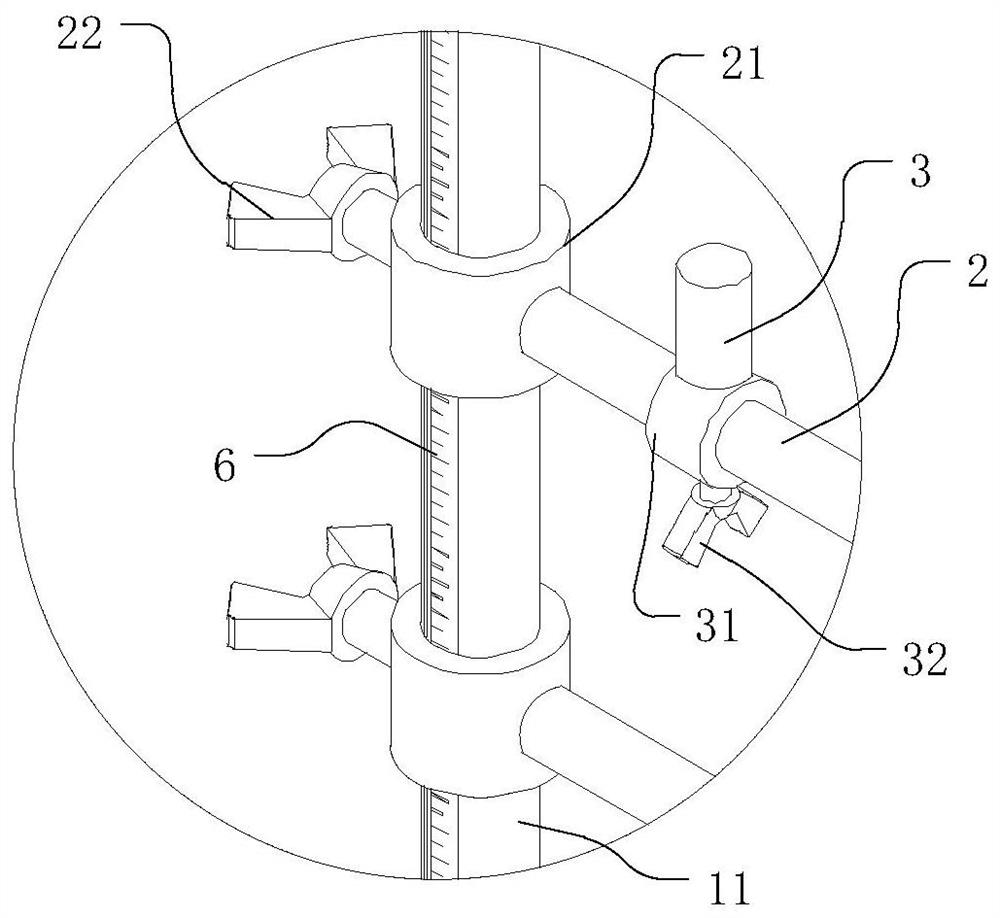
[0030] The structure of this embodiment is the same as that of the bracket 1 of the first embodiment, and the difference from the first embodiment is that the heights of the multiple horizontal positioning rods 2 of the first horizontal positioning rod group and the second horizontal positioning rod group are movable and adjustable. On the support 1, the positioning column 3 is set on the horizontal positioning rod 2 in a movable and adjustable manner, and the height of the pallet frame is set on the support 1 in a movable and adjustable manner.

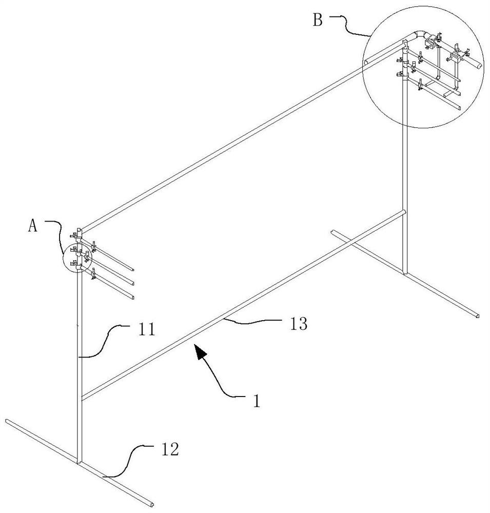
[0031] refer to Figure 2-5, the present embodiment also takes a pile-cut reinforcement cage with 6 vertical steel bars 71 as an example, and describes the welding device applicable to this kind of pile-cut reinforcement cage. Three horizontal positioning rods 2 are arranged on the upper end of each vertical rod 11 respectively, and the heights of the three horizontal positioning rods 2 on the vertical rod 11 can be adjusted. Specif...


PUM


Abstract

The invention relates to a welding device for a pile-cut reinforcement cage, which includes a bracket, a first horizontal positioning rod group, a second horizontal positioning rod group and a pallet frame arranged on the bracket, the first horizontal positioning rod group and the second horizontal positioning rod group The rod groups are set at a preset distance from each other and are arranged correspondingly. The first horizontal positioning rod group and the second horizontal positioning rod group are used in conjunction with each other to arrange and support multiple vertical steel bars and supporting plates when welding the pile-cut reinforcement cage. The frame and the second horizontal positioning rod group are respectively located on the opposite sides of the first horizontal positioning rod group, and the pallet frame is arranged adjacent to the first horizontal positioning rod group, and the pallet frame is used to place and support the pile-cut reinforcement cage when welding pallet. The welding device can make the vertical steel bars evenly arranged and play a good supporting role on the vertical steel bars. The problem of vertical steel bar tilting will not occur during welding, and can significantly improve the welding process quality and welding speed of the pile-cut steel bar cage. The welding operation of the pile-cut reinforcement cage is convenient and safe.

Description

technical field [0001] The invention relates to the technical field of building construction components, and more specifically, to a welding device for a pile-cut reinforcement cage. Background technique [0002] With the rapid development of domestic infrastructure, steel cages are becoming more and more common in pile foundation construction. The cut pile is directly opened on the designed pile position, and its cross-section is circular. After the hole is formed, a steel cage is placed in the hole and concrete is poured. The pile-cut reinforcement cage includes a support plate and multiple vertical reinforcement bars. The vertical reinforcement bars are evenly distributed on the circumference and one end is welded on the support plate. The vertical reinforcement cage of the pile-cut reinforcement cage has a larger diameter and a longer length. Among them, due to the heavy weight, the vertical steel bar is prone to inclination during welding, and the operation during weld...

Claims


Application Information

Patent Timeline
Patent Type & Authority Patents(China)
IPC IPC(8): B23K37/04
CPCB23K37/0426
Inventor 柳建国
Owner MCC5 GROUP SHANGHAI CORPORATION LIMITED
Why Eureka
Try Eureka