
Buffer-type magnetic door stopper

A door stopper and magnetic technology, applied in door/window accessories, building fastening devices, wing leaf fastening devices, etc., can solve the problems of poor use effect, magnetic block wall peeling, etc., to prolong the service life, Avoid collisions and improve the effect of adsorption

Active Publication Date: 2019-07-30
东海县常春门窗有限公司
View PDF6 Cites 14 Cited by
  • Summary
  • Abstract
  • Description
  • Claims
  • Application Information

AI Technical Summary

Problems solved by technology

[0003] At present, most of the door stoppers adopt the magnetic adsorption type. However, when this kind of door stopper is in use, the two magnets will be directly adsorbed, and violent collision will occur. In the long run, the magnetic block and even the wall skin will fall off. Poor use

Method used

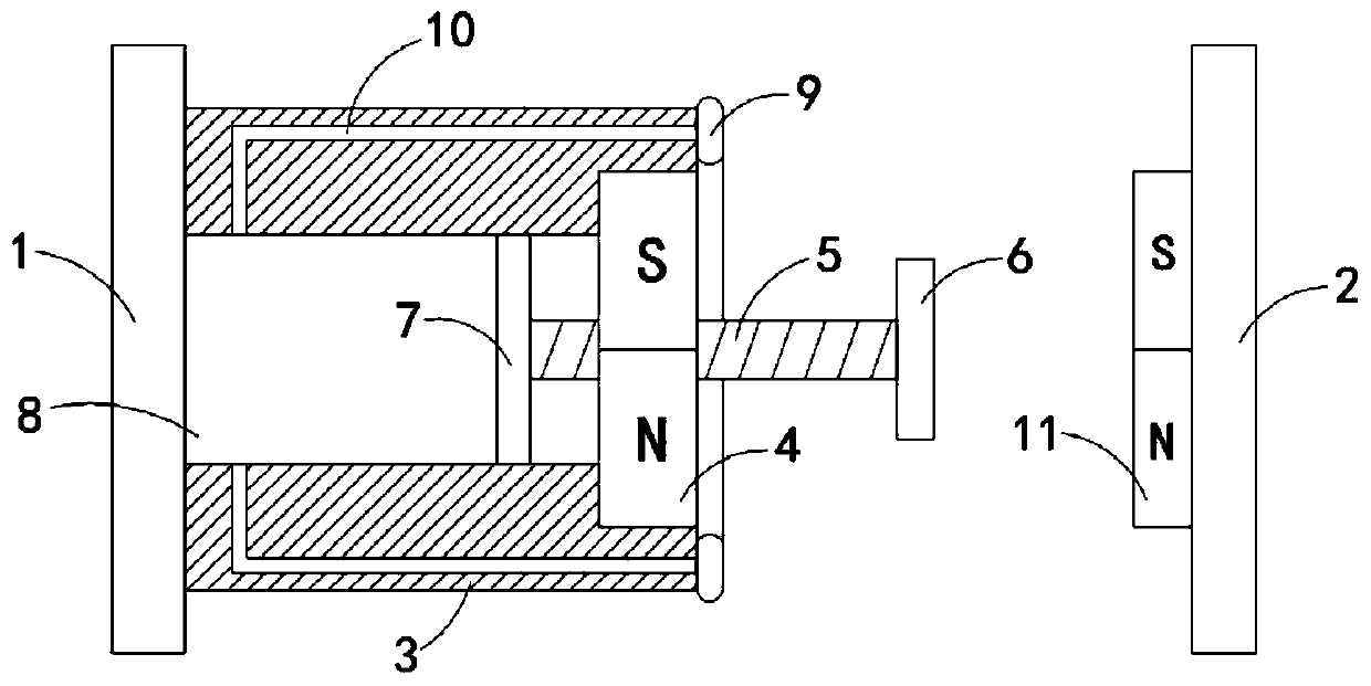
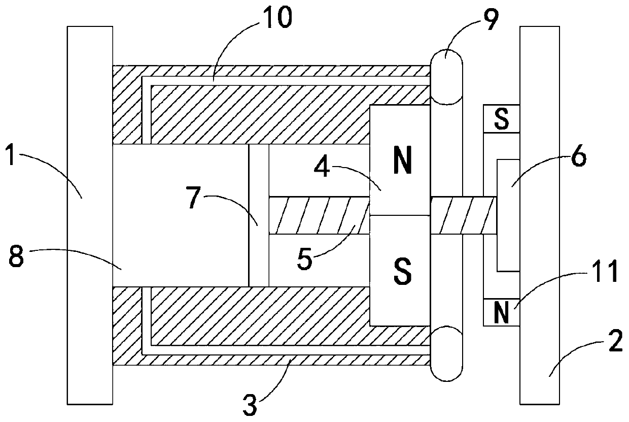
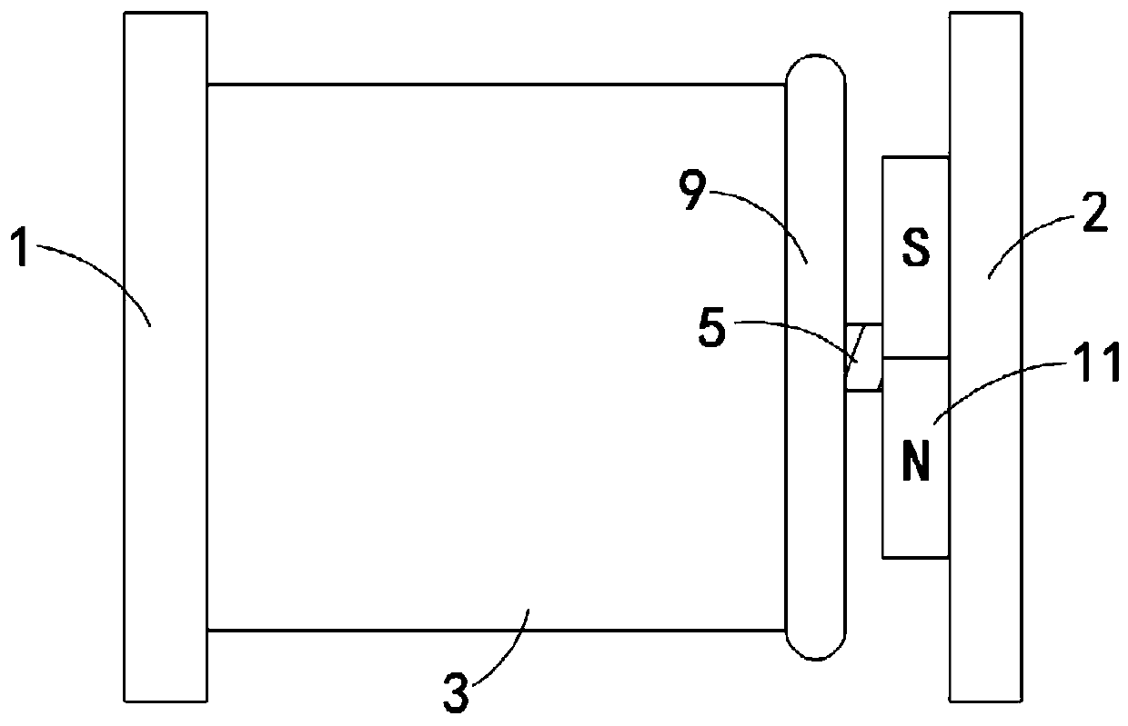

Image

  • Buffer-type magnetic door stopper
  • Buffer-type magnetic door stopper
  • Buffer-type magnetic door stopper

Examples


Embodiment 1

[0022] like Figure 1-3 As shown, a buffer type magnetic door stopper includes a first connecting plate 1 fixedly installed on the door body and a second connecting plate 2 fixedly installed on the wall, the side wall of the first connecting plate 1 is fixedly connected with Cylinder body 3, grooves are provided on the end surface of cylinder body 3 away from the first connecting plate 1, and permanent magnet rotating ring 4 is rotatably connected in the groove, and threaded holes are formed on the permanent magnet rotating ring 4, and the threaded holes are internally threaded. There is a screw rod 5, one end of the screw rod 5 located outside the cylinder body 3 is fixedly connected with a buffer block 6, and one end of the screw rod 5 located inside the cylinder body 3 is fixedly connected with a sealing plate 7, and the sealing plate 7 slides with the inner side wall of the cylinder body 3 Sealed connection, the side wall of the sealing plate 7 away from the screw rod 5 fo...

Embodiment 2

[0026] like Figure 4-5 As shown, the difference between this embodiment and Embodiment 1 is that a fixed ring 12 is provided between the permanent magnet rotating ring 4 and the sealing plate 7, and the fixed ring 12 is fixedly connected with the inner side wall of the cylinder body 3, and the fixed ring 12 and the A plurality of telescopic bellows 13 are fixedly connected between the sealing plates 7, and the telescopic bellows 13 expand and contract along the axial direction thereof. The hole 14 and the buffer block 6 are arranged in a cover shape. Specifically, the buffer block 6 is made of elastic rubber, and the inside of the buffer block 6 communicates with the end of the screw rod 5 away from the sealing plate 7 .

[0027] In this embodiment, when the sealing plate 7 moves to the inside of the cylinder body 3, since the position of the fixed ring 12 is fixed, the telescopic bellows 13 will be elongated, so that the telescopic bellows 13, the hollow screw rod 5 and the ...


PUM


Abstract

The invention belongs to the field of construction, and particularly relates to a buffer-type magnetic door stopper. The buffer-type magnetic door stopper comprises a first connecting plate fixedly mounted on a door body, and a second connecting plate fixedly mounted on a wall body; the side wall of the first connecting plate is fixedly connected with a cylinder, and a groove is formed in the endface, away from the first connecting plate, of the cylinder; a permanent magnetic rotating ring is rotatably connected into the groove, and a threaded hole is formed in the permanent magnetic rotatingring in a penetrating mode; a lead screw is connected into the threaded hole in a threaded mode, the end, outside the cylinder, of the lead screw is fixedly connected with a buffer block, and the end, in the cylinder, of the lead screw is fixedly connected with a sealing plate; the sealing plate and the inner side wall of the cylinder are slidably connected in a sealed mode, and the side wall, away from the lead screw, of the sealing plate and the cylinder form a sealed space; and the side wall, away from the first connecting plate, of the cylinder is fixedly connected with an annular bufferairbag, and the sealed space communicates with the annular buffer airbag through a plurality of channels. The buffer effect is good, magnets can be effectively prevented from being directly collided,and the service life of the door stopper is prolonged.

Description

technical field [0001] The invention belongs to the field of construction, in particular to a buffer type magnetic door stopper. Background technique [0002] The door stopper is a buffer device used between the door body and the wall. On the one hand, it can fix the door body, and on the other hand, it can prevent the door handle and other components from directly colliding with the wall body, causing damage to the door body or the wall surface. [0003] At present, most of the door stoppers adopt the magnetic adsorption type. However, when this kind of door stopper is in use, the two magnets will be directly adsorbed, and violent collision will occur. In the long run, the magnetic block and even the wall skin will fall off. The use effect is poor. [0004] Therefore, we propose a buffered magnetic door stopper to solve the above problems. Contents of the invention [0005] The object of the present invention is to solve the above problems and provide a buffer magnetic ...

Claims


Application Information

Patent Timeline
Patent Type & Authority Applications(China)
IPC IPC(8): E05C17/56E05F5/06
CPCE05C17/56E05F5/06
Inventor 左莉莉
Owner 东海县常春门窗有限公司
Learn More