Solar cell lamination control device

A technology of solar cells and control devices, which is applied in the field of solar cells, can solve problems such as difficult to realize, and achieve the effects of improving flexibility, reducing investment costs, and increasing the scope of application

Active Publication Date: 2019-07-30
HENAN INST OF ENG
View PDF5 Cites 0 Cited by
  • Summary
  • Abstract
  • Description
  • Claims
  • Application Information

AI Technical Summary

Problems solved by technology

The lamination process of solar panels is mainly completed by a laminator, but the laminator researched at home and abroad can only laminate panels with a planar structure. For panels with three-dimensional requirements, existing Laminators are difficult to realize, such as: solar panels on the roof of solar car air conditioning

Method used


Image

  • Solar cell lamination control device
  • Solar cell lamination control device
  • Solar cell lamination control device

Examples


Embodiment

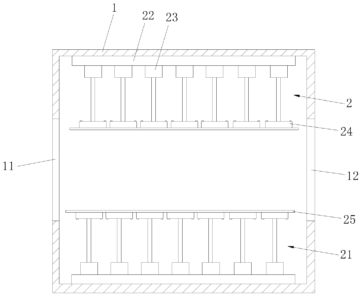
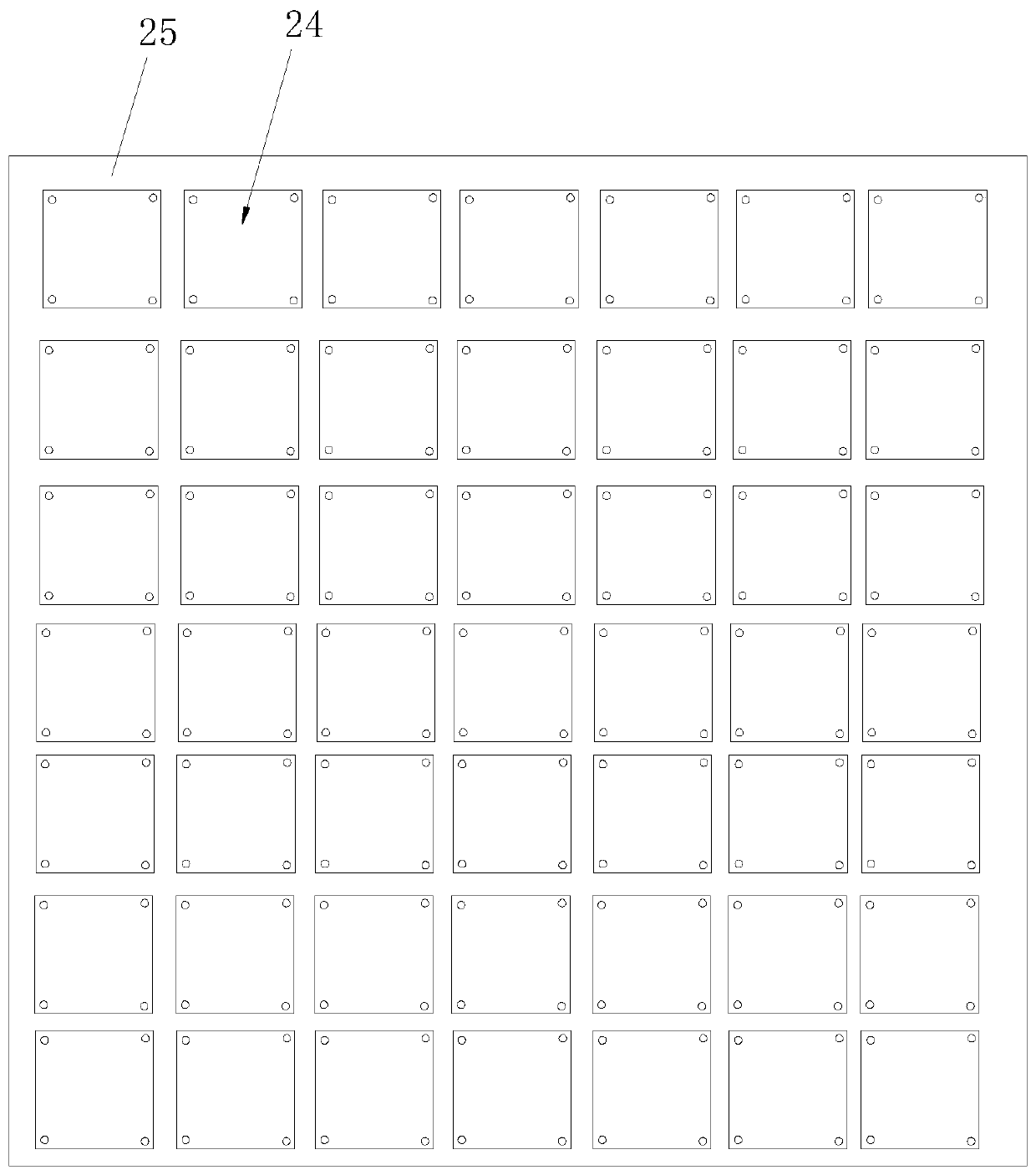
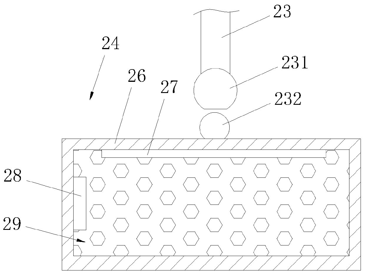
[0029] Example: A solar cell lamination control device, such as figure 1 versus Figure 4 As shown, the cabinet 1 and the host computer 3 are included. The symmetrical sides of the cabinet 1 are provided with an inlet 11 and an outlet 12 respectively. An upper laminate assembly 2 is installed on the inner top wall of the box body 1, a lower laminate assembly 21 is installed on the inner bottom surface of the box body 1, and the upper laminate assembly 2 and the lower laminate assembly 21 are arranged symmetrically. Both the upper lamination assembly 2 and the lower lamination assembly 21 include a base 22, a pressure pad 25 and a main controller 31. A plurality of vertically arranged driving cylinders 23 are arranged on the surface of the base 22, and the output shafts of the driving cylinders 23 correspond to each other. A heating element 24 is provided, and the pressure pad 25 is fixedly connected to the surface of the heating element 24 facing away from the driving cylinder 2...


PUM


Abstract

The invention discloses a solar cell lamination control device, relates to the technical field of solar cells, and solves the problem that an existing lamination device cannot meet the requirements ofcurved solar cell panels. The technical scheme is as follows: the solar cell lamination control device comprises a box body and an upper computer; an upper lamination assembly and a lower laminationassembly are symmetrically arranged in the box body; each of the upper lamination assembly and the lower lamination assembly comprises a base, a pressure pad and a main controller; a plurality of vertically-arranged driving air cylinders are distributed on the surface of the base; heating pieces are arranged on output shafts of the driving air cylinders in a one-to-one correspondence mode; the pressure pad is fixedly connected with the surfaces, back to the driving air cylinders, of the heating pieces; the driving air cylinders and the heating pieces are electrically connected with the main controller; and the main controller is in communication connection with the upper computer. The solar cell lamination control device has the advantages that the curved solar cell panels can be laminated, the application range of the laminated solar cell panels is expanded, the investment cost of solar cell panel lamination is reduced, and the like.

Description

Technical field [0001] The invention relates to the technical field of solar cells, and more specifically, it relates to a solar cell lamination control device. Background technique [0002] Solar cells, also known as "photocells", are photoelectric semiconductor sheets that use sunlight to directly generate electricity. As long as it is exposed to light that meets certain illuminance conditions, it can instantly output voltage and generate current when there is a loop. This phenomenon is called photovoltaic effect (Photovoltaic effect, abbreviated as PV) in physics. [0003] At present, in the production process of solar panels, lamination is a very critical process. The main process is to place the multilayer solar cell modules and colloids under a certain temperature and vacuum to melt and solidify the colloids to achieve The purpose of component bonding. The lamination process of solar panels is mainly completed by laminators, but the laminators currently developed at home a...

Claims


Application Information

Patent Timeline
Patent Type & Authority Applications(China)
IPC IPC(8): H01L31/18H01L31/048
CPCH01L31/048H01L31/1876Y02E10/50Y02P70/50
Inventor 朱彤珺云天英
Owner HENAN INST OF ENG
Why Eureka
Try Eureka