Friction feeder

A feeding device and friction-type technology, which is applied in the field of friction-type yarn feeding devices, can solve problems such as complex adjustment of yarn delivery, inaccuracy or error in knitting processing, and error in fabric products, and achieve the effect of reducing friction interference

Inactive Publication Date: 2019-07-30
SIPRA PATENTENTWICKLUNGS & BETEILIGUNGSGMBH
View PDF8 Cites 6 Cited by
  • Summary
  • Abstract
  • Description
  • Claims
  • Application Information

AI Technical Summary

Problems solved by technology

This causes the yarn guide to react against the feed force transmitted to the yarn by the surface of the delivery roller due to the friction generated in the deflection, thus affecting not only the effect of the yarn delivery itself, but also the uniformity achieved by means of the yarn feeding device. Negative impact on maintenance of yarn tension
Irregularities in yarn tension may in turn cause inaccuracies or errors in the knitting process, which in turn lead to errors in the processed fabric product
Furthermore, the adjustment of the yarn delivery in DE 35 06 552 A1 is complicated for the operator due to the use of a number of adjustable yarn guides whose positioning relative to each other is decisive

Method used


Image

  • Friction feeder
  • Friction feeder
  • Friction feeder

Examples


Embodiment Construction

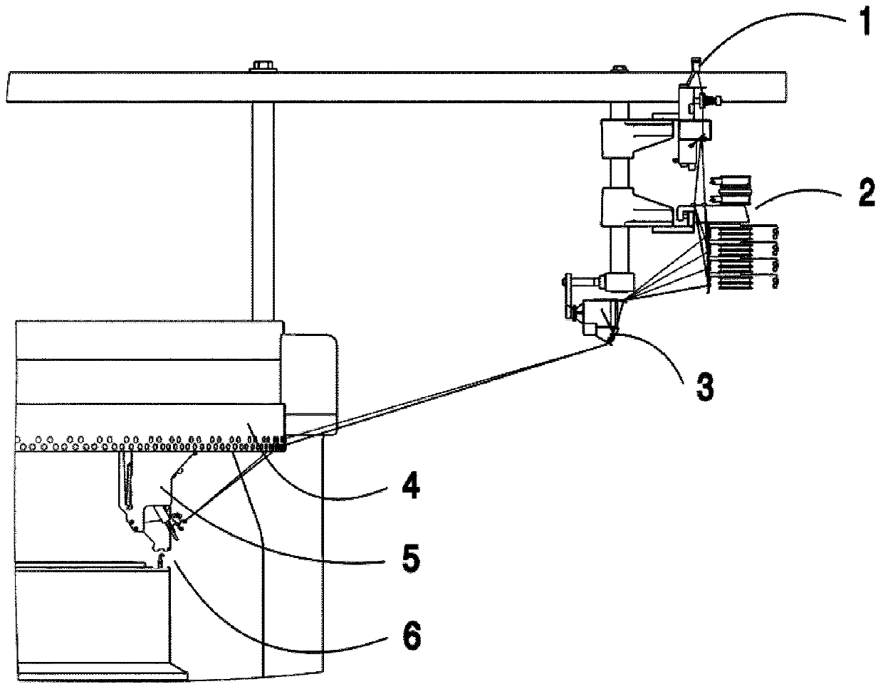
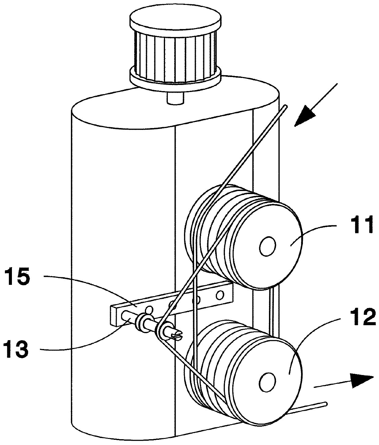
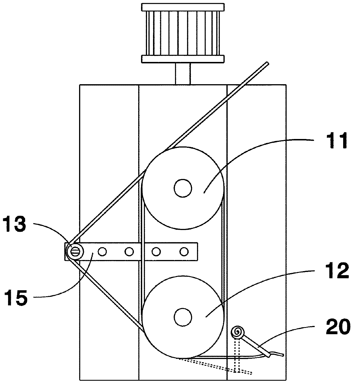
[0033] In circular knitting machines with pick-up devices, several (for example four or six) yarns pass through each yarn feeder under the control of yarn selection on the pick-up device, but at each time Only one yarn is processed on each point, while the other yarns are disconnected. In this regard, figure 2 and image 3 (in which only one yarn passes through the yarn feeder to illustrate the yarn path in the frictional yarn feeder according to the invention) shows only a sub-aspect of an embodiment of the frictional yarn feeder according to the invention, which Friction Yarn Feed Replacement figure 1 Shown is a conventional friction yarn feeding device in a conventional circular knitting machine with yarn picking function.

[0034] The frictional yarn feed device according to the invention has two delivery rollers 11 , 12 which are held in a recumbent manner (ie with a horizontal axis) and parallel to each other. The conveying rollers are preferably arranged one above ...


PUM


Abstract

The invention relates to a friction feeder for receiving a plurality of threads from one or more corresponding thread delivery devices and feeding at least one of the threads to a thread-processing point of a knitting machine. At least two rollers arranged parallel to each other receive the threads and transport the threads in that the threads are carried along by the rollers by friction on the roller surfaces. A deflecting element is used to adjust the carry-along force applied by the rollers to at least one of the threads, wherein the rollers are arranged in such a way that the threads can be wrapped around both together at least once. The deflecting element can be set in such a way that the deflecting element deflects the thread or threads in a section of the course of the thread wrap between the rollers in such a way that the angle of wrap of the thread or threads around the rollers and thus the contact length of the thread or threads with the roller surfaces can be increased or decreased.

Description

technical field [0001] The invention relates to a friction yarn feed device for a knitting machine handling several yarns, in particular a circular knitting machine with a yarn pick-up device. Background technique [0002] figure 1 It is a schematic side view of the yarn guidance at a single knitting point in such a conventional circular knitting machine with a yarn picking device 5 . [0003] The yarn to be processed is conveyed to the knitting point 6 by means of the yarn monitor 3 and the yarn guide ring 4 from the yarn feeding device 2 which pulls the yarn out of the bobbin through the yarn feeding device 1 and It also ensures that proper yarn tension is maintained. In this case, the required yarn tension depends primarily on the yarn material used. Furthermore, in the case of knitting machines with a jacquard function, the amount of yarn reduction at the knitting point varies, which causes fluctuations in yarn tension. The yarn feed must compensate for such fluctuat...

Claims


Application Information

Patent Timeline
IPC IPC(8): D04B15/48B65H51/12
CPCB65H51/12B65H2701/31D04B9/30D04B15/48
Inventor D·特伦克勒
Owner SIPRA PATENTENTWICKLUNGS & BETEILIGUNGSGMBH
Why Eureka
Try Eureka