Unlock instant, AI-driven research and patent intelligence for your innovation.
Flexible electromagnetic wave shielding material, electromagnetic wave shielding type circuit module comprising same and electronic device furnished with same
What is Al technical title?
Al technical title is built by PatSnap Al team. It summarizes the technical point description of the patent document.
This helps you quickly interpret patents by identifying the three key elements:
Problems solved by technology
Method used
Benefits of technology
Problems solved by technology
On the other hand, an example of the electromagnetic wave shielding material may be a metal cover or a metal plate. This electromagnetic wave shielding material is difficult to exhibit flexibility and stretchability. Ease of adoption in diverse applications
In particular, electromagnetic wave shielding materials such as metal plates or metal films are difficult to adhere to components that are sources of electromagnetic waves or components that need to be protected from sources of electromagnetic waves without gaps. cracks, it will be difficult to fully express the electromagnetic wave shielding performance
[0006] In order to solve this problem, an electromagnetic wave shielding material in which a conductive coating is formed on a lightweight support member such as a polymer film has recently been introduced. There is a limit in performance. Due to the lack of flexibility, a film with a predetermined thickness or more is difficult to fit tightly on parts with misalignment and unevenness. After it is made into a specific shape, it is difficult to deform the shape freely. Even if the shape is deformable When the shape is deformed, there are problems such as frequent cracks and peeling of the coated conductive coating.
Method used
Image
Click on the blue label to locate the original text in one second.
Reading with bidirectional positioning of images and text.
Examples
Embodiment 1
[0219] In 88 g of dimethylacetamide and acetone at a weight ratio of 70:30, 12 g of polyvinylidene fluoride was dissolved at a temperature of 80° C. for 6 hours using a magnetic bar to prepare a spinning solution. In the spinning solution, as a conductive filler, spherical silver particles with an average particle diameter of 1.3 μm are mixed so that the volume ratio of polyvinylidene fluoride to silver particles is 1:0.2, accounting for 16.7% of the total volume of the final fiber part, Then, it was dispersed for 12 hours using an ultrasonic disperser. Put the spinning solution into the solution tank of the electrospinning device, stir the solution with an impeller, and spit it out at a speed of 20 μl / min / hole. At this time, the temperature in the spinning section is kept at 30°C, the humidity is kept at 50%, the distance between the collector and the tip of the spinning nozzle is 20cm, and a high voltage generator is used to apply a voltage of 40kV to the spinning nozzle gro...
Embodiment 2~11
[0222] It carried out and produced similarly to Example 1, but as shown in Table 1 or Table 2 below, the content and particle diameter of a conductive filler were changed, and the conductive fiber web shown in Table 1 below was manufactured.
experiment example 1
[0226] The following physical properties were measured for the conductive webs of Examples 1 to 11 and Comparative Example 1, and are shown in Table 1 and Table 2 below.
[0228] The impedance of the surface of the conductive fiber web was measured by an impedance measuring instrument (Hiki 3540 mΩ HITESTER, Hiki Co., Ltd.). With the measured value of Comparative Example 1 being 100 as a reference, the measured impedance values of Examples are shown as relative percentages.
[0229] 2. Variation rate of electromagnetic wave shielding performance
[0230] Using jigs, stretch the test piece 1.2 times in the transverse direction, and then stretch it 1.2 times in the longitudinal direction, taking this as one group and repeating three groups.
[0231] Then, using the initial electromagnetic wave shielding performance measurement method, after obtaining the impedance value B of each test piece after stretching, accord...
PUM
Property
Measurement
Unit
diameter
aaaaa
aaaaa
porosity
aaaaa
aaaaa
diameter
aaaaa
aaaaa
Abstract
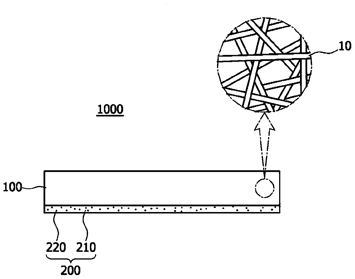
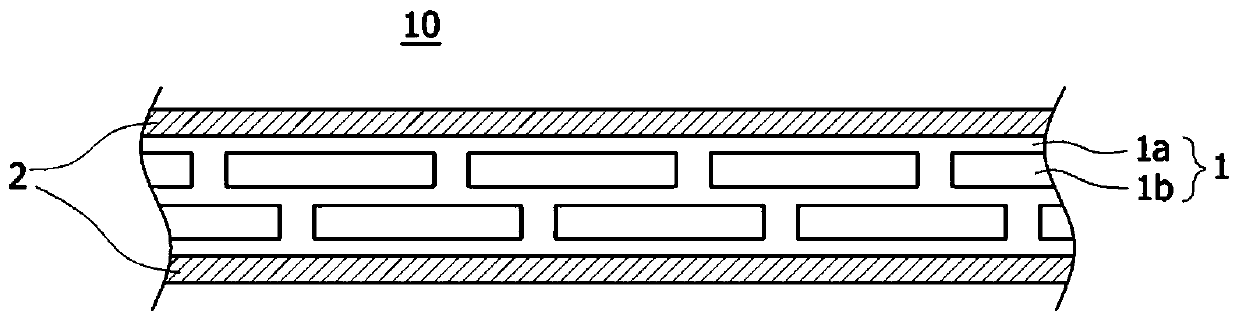
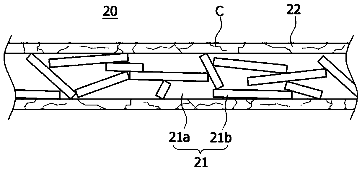
The present invention provides a flexible electromagnetic wave shielding material. An electromagnetic wave shielding material, according to one embodiment of the present invention, comprises: a conductive fiber web including conductive composite fibers comprising a metal shell part coated on the outside of a fiber part to form a plurality of pores; and a first conductive component provided in at least some of the pores. Due to these features, as the electromagnetic wave shielding material has excellent elasticity, and creasing / recovery, it is possible to freely modify the shape thereof as desired and to attach the electromagnetic wave shielding material to be completely adhered to a surface even if the surface where the material is to be disposed has a curved shape such as uneven or stepped surfaces, and thus it is possible to exhibit excellent electromagnetic wave shielding performance. In addition, degradation of the electromagnetic wave shielding performance can be prevented even with various shape changes. Furthermore, even when parts are mounted with a high density in a narrow area, the electromagnetic wave shielding material can be provided to completely adhere to the mountedparts while overcoming tight spacing intervals and steps between the parts, such that the flexible electromagnetic wave shielding material can easily be adopted in a compact or flexible electronic device.
Description
technical field [0001] The present invention relates to an electromagnetic wave shielding material, and more specifically, to a flexible electromagnetic wave shielding material excellent in flexibility, stretchability, and wrinkle / restorability, an electromagnetic wave shielding circuit module including the same, and an electronic device including the same. Background technique [0002] Electromagnetic waves are a phenomenon in which energy moves in the form of sinusoidal waves while electric and magnetic fields interact with each other, and are usefully used in electronic equipment such as wireless communication or radar. The electric field is generated by voltage and is easily shielded due to long distance or obstacles such as trees. On the contrary, the magnetic field is generated by current and is inversely proportional to distance, but has the characteristic of being difficult to be shielded. [0003] Recent electronic equipment is sensitive to electromagnetic interfere...
Claims
Application Information
Patent Timeline
Application Date:The date an application was filed.
Publication Date:The date a patent or application was officially published.
First Publication Date:The earliest publication date of a patent with the same application number.
Issue Date:Publication date of the patent grant document.
PCT Entry Date:The Entry date of PCT National Phase.
Estimated Expiry Date:The statutory expiry date of a patent right according to the Patent Law, and it is the longest term of protection that the patent right can achieve without the termination of the patent right due to other reasons(Term extension factor has been taken into account ).
Invalid Date:Actual expiry date is based on effective date or publication date of legal transaction data of invalid patent.

