A vacuum cleaner and a control method thereof

A control method and technology for vacuum cleaners, applied in the installation of vacuum cleaners, suction filters, electrical equipment, etc., can solve the problems of insufficient dust removal effect, troublesome cleaning of dust collectors, poor liquid separation effect, etc., to improve user experience and compact structure. , Improve the effect of vacuuming efficiency

Inactive Publication Date: 2019-08-02
SUZHOU GAMANA ELECTRIC APPLIANCE CO LTD
View PDF6 Cites 19 Cited by
  • Summary
  • Abstract
  • Description
  • Claims
  • Application Information

AI Technical Summary

Problems solved by technology

[0004] The filter system in the vacuum cleaner products in the prior art includes a tornado system, a single cone filter system and sponge, hypa and dust bag filters, and the vacuum cleaner usually only has one motor for suction, the dust removal effect is not outstanding enough, and the separation of liquid The effect is poor, and the cleaning of the dust collection device is also very troublesome, which reduces the user experience

Method used


Image

  • A vacuum cleaner and a control method thereof
  • A vacuum cleaner and a control method thereof
  • A vacuum cleaner and a control method thereof

Examples


Embodiment 1

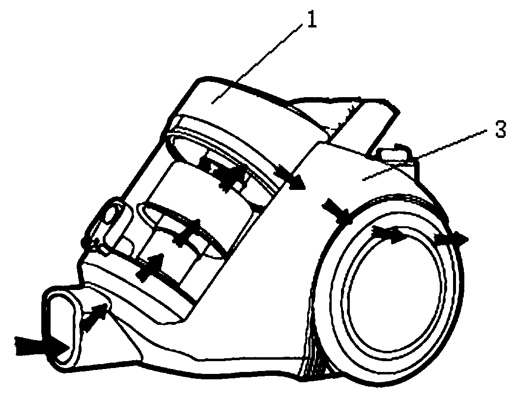
[0041] In order to solve the problems existing in the prior art, this embodiment provides a structure of the vacuum cleaner, specifically, refer to Figure 1 to Figure 4, the vacuum cleaner includes a dust collection device 1 and a main body 3, the dust collection device 1 is detachably installed on the main body 3, the dust collection device 1 is used to separate and collect garbage; the main body 3 is provided with Suction motor and fan, the suction motor starts behind the drive motor 15 and stops earlier than the drive motor 15, the suction motor drives the fan to rotate to generate suction, and the dusty air is sucked to the In the main body 3 of the vacuum cleaner.

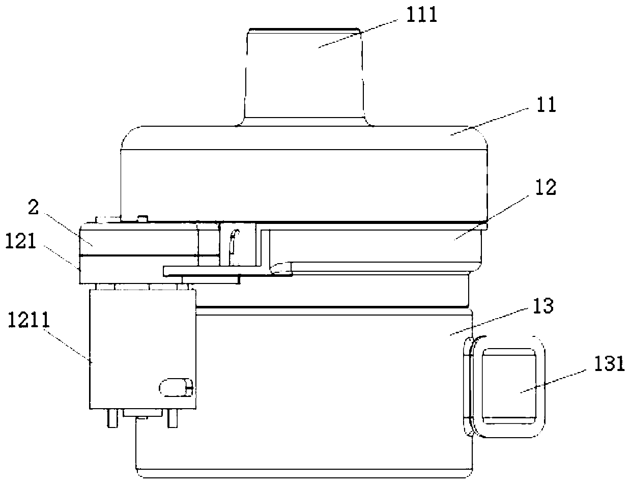
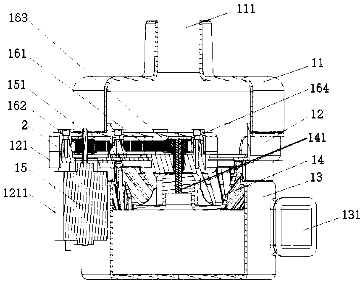
[0042] In an implementable solution, the dust collecting device 1 includes a driving motor 15, a separator 14, a separator driving device 16, a housing 11, a partition support 12 and a dust cup 13, and the driving motor 15 passes through the The separator driving device 16 drives the separator 14 to rotate, ...

Embodiment approach

[0053] As an embodiment, the dust collecting device 1 further includes a sealing cover 2, and the sealing cover 2 is closed and connected with the partition bracket 12 to form a cavity.

[0054] The support part 121 has a first through hole, the output shaft 151 of the driving device 15 enters the cavity through the first through hole, and is connected with the first transmission wheel 162; 12 has a second through hole, the rotating shaft 164 enters the cavity through the second through hole, and is connected with the second transmission wheel 163 . The supporting part 121 further includes a box body 1211 for accommodating the driving motor 15 .

[0055] As an embodiment, a plurality of positioning parts are arranged in the cavity, which are used to limit the movement track of the transmission belt, fix the position of the transmission belt, and prevent the transmission belt from coming out. In a possible implementation manner, the positioning member is a positioning column, ...

Embodiment 2

[0072] In order to solve the problems existing in the prior art, this embodiment provides another structure of the vacuum cleaner. Specifically, in this embodiment, please refer to the detailed description of Embodiment 1 for details not involved in this embodiment.

[0073] Specifically, in this embodiment, participating Figure 5 to Figure 7 , the housing 11 is connected to the dust cup 13, the partition bracket 12 is arranged in the accommodating cavity formed by the housing 11 and the dust cup 13, and the partition bracket 12 includes a partition and a connecting cylinder, the partition is provided with a first hollow structure for the passage of fluid, one side of the partition is connected to the housing, and the other side of the partition is connected to the connecting cylinder, the The connecting cylinder extends into the dust cup.

[0074] Further, in this embodiment, the axis of the driving motor 15 coincides with the rotation axis of the separator 14 , and the dri...


PUM


Abstract

The invention relates to the technical field of dust collectors, and discloses a dust collector and a control method thereof, the dust collector comprises a dust collecting device and a main body, thedust collecting device is detachably mounted on the main body, and the dust collecting device is used for separating and collecting garbage; the dust collecting device comprises a driving motor and aseparator, and the driving motor drives the separator to rotate; an air suction motor is arranged in the main body, when the dust collector is started, the air suction motor falls behind the drivingmotor to be started, and when the dust collector stops, the air suction motor stops earlier than the driving motor. Through arrangement of the driving motor and the air suction motor, the driving motor drives the separator to rotate to reach the preset rotating speed, then the dust collector sucks in fluid under the action of the air suction motor, and the separation effect of the fluid for removing dust and liquid is effectively improved.

Description

technical field [0001] The invention relates to the technical field of vacuum cleaners, in particular to a vacuum cleaner and a control method for the vacuum cleaner. Background technique [0002] Vacuum cleaners can be divided into vertical, horizontal and portable according to their structure. The working principle of the vacuum cleaner is to use the motor to drive the blades to rotate at high speed, generate air negative pressure in the sealed housing, and absorb dust. [0003] At present, more and more families choose horizontal vacuum cleaners as cleaning tools. Horizontal vacuum cleaners are mainly composed of floor brushes, connecting conduits, dust collection devices, casings and motor components. The dust collection devices include dust cups and separators. The motor assembly has a motor air inlet and a motor air outlet, and the motor assembly is used to generate suction, which sucks impurities on the ground and surrounding air into the dust chamber of the dust col...

Claims


Application Information

Patent Timeline
Patent Type & Authority Applications(China)
IPC IPC(8): A47L9/28A47L9/10
CPCA47L9/102A47L9/106A47L9/2836A47L9/2889
Inventor 杨曾峥陈先鄂
Owner SUZHOU GAMANA ELECTRIC APPLIANCE CO LTD
Why Eureka
Try Eureka