Bottle

A bottle and bottle-shaped technology, applied in the direction of packaging food, packaging, medical containers, etc., can solve the problem of uneven liquid discharge, and achieve the effects of uniform liquid discharge, simple structure and improved sealing effect.

Pending Publication Date: 2019-08-02
台州屹达塑业有限公司
View PDF2 Cites 0 Cited by
  • Summary
  • Abstract
  • Description
  • Claims
  • Application Information

AI Technical Summary

Problems solved by technology

[0005] However, whether it is a bottle using the above-mentioned elastic sealing method or a bottle using the above-mentioned rotary sealing method, it is limited to the way of liquid discharge in the center, resulting in the problem of uneven liquid discharge.

Method used


Image

  • Bottle
  • Bottle
  • Bottle

Examples


Embodiment 1

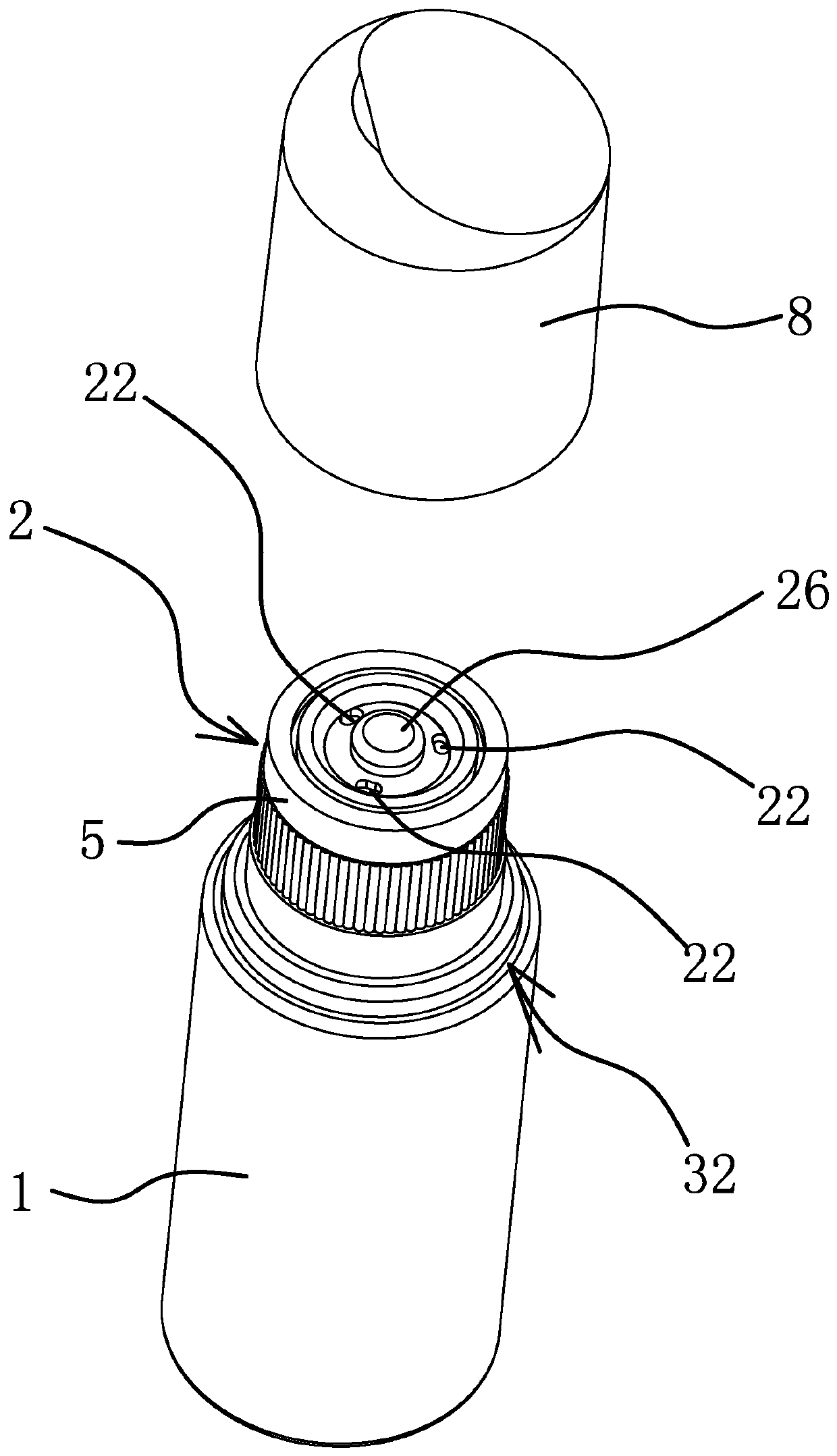
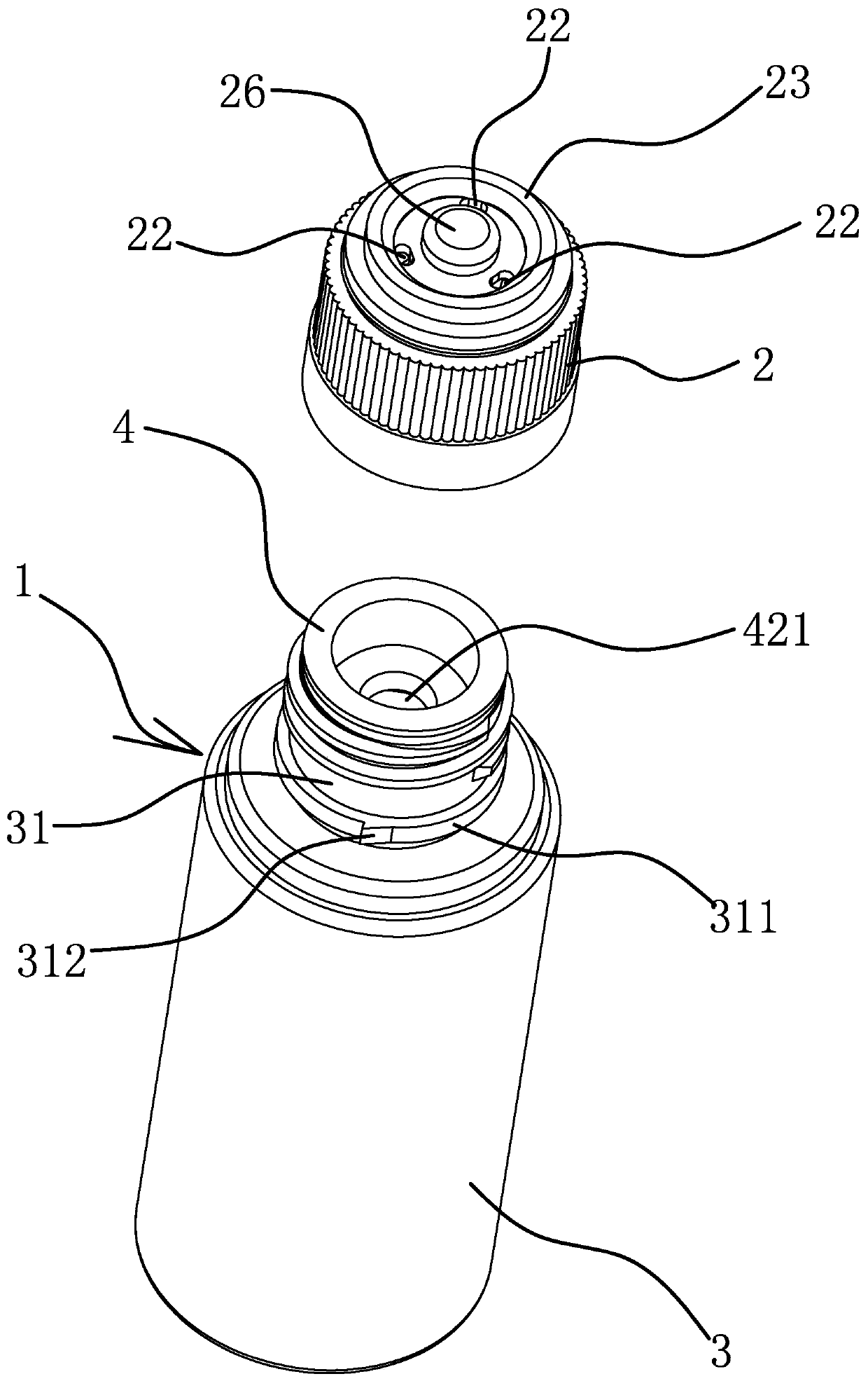
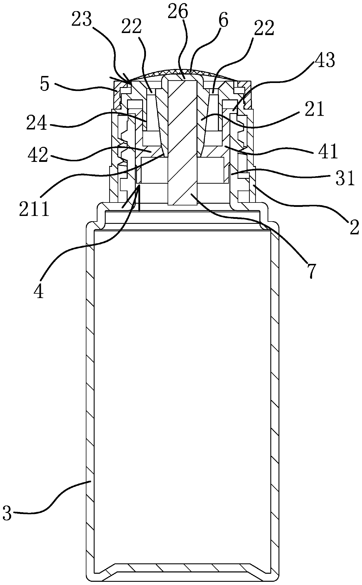
[0047] Such as Figure 1-Figure 3 As shown, a bottle includes a bottle-shaped body 1 and a rotatable inner cover 2 connected to the upper end of the body 1. The upper end of the body 1 is provided with a liquid hole 421 communicating with the inner cavity of the body 1. When the inner cover 2 rotates, it can Move up and down to open or close the liquid hole 421 , and a limiting structure capable of limiting the rotation angle of the inner cover 2 is provided between the inner cover 2 and the main body 1 . In this embodiment, the body 1 specifically includes a bottle body 3 with a mouth 31 and a bottle stopper 4 fixed in the mouth 31 , a liquid hole 421 is provided inside the bottle stopper 4 , and an inner cap 2 is connected to the outside of the mouth 31 The outer side of the bottle body 3 is provided with an annular socket 32 ​​below the mouth 31, and the bottle also includes a bottle cap 8 that can be placed on the annular socket 32 ​​and cover the inner cap 2.

[0048] Su...

Embodiment 2

[0063] The structure and principle of this embodiment are basically the same as that of Embodiment 1, the difference is that in this embodiment, the position-limiting structure includes a protruding column arranged outside the mouth 31 and a spiral guide groove arranged inside the inner cover 2, The boss is located in the spiral guide groove and can move along the spiral guide groove. The cooperation between the boss and the threaded guide groove enables the inner cover 2 to move up or down while turning, and at the same time, the inner cover 2 is restricted when the boss moves along the spiral guide groove until it abuts against the inner walls at both ends of the spiral guide groove Turning, the inner cap 2 reaches the maximum distance of upward or downward movement, which can prevent the inner cap 2 from completely detaching from the mouth portion 31 and invalidate the entire structure of the bottle.

Embodiment 3

[0065] The structure and principle of this embodiment are basically the same as that of Embodiment 1, except that in this embodiment, the outer diameter of the annular convex portion 24 is smaller than the inner diameter of the cylindrical body 41, and a sealing ring is provided on the inner side of the upper end of the cylindrical body 41, and the inner side of the sealing ring is The wall abuts against the outer side wall of the annular protrusion 24 to form a seal.


PUM


Abstract

The invention provides a bottle, belonging to the technical field of containers. The invention aims to achieve the purpose of making liquid outlet more uniform while increasing the sealing property. The bottle comprises a bottle-shaped body and an inner cap connected to the upper end of the body and being capable of rotating, the inner cap can move along the up-down direction while rotating, the upper end of the body is provided with a liquid-passing hole communicated with the inner cavity of the body, the center of the top wall of the inner side of the inner cap is provided with a sealing portion, the outer side of the sealing portion is provided with a sealing cone, the sealing portion stretches into the liquid-passing hole, the sealing cone attaches to the inner wall of the liquid-passing hole to form sealing, when the inner cap moves upwards, the sealing cone separates from the inner wall of the liquid-passing hole to open the liquid-passing hole, and the upper end surface of the inner cap is provided with a plurality of liquid outlet holes distributed around the sealing portion. The bottle has the advantages that the overall structure is more compact and reasonable, the sealing effect is improved, and the sealing reliability is guaranteed.

Description

technical field [0001] The invention belongs to the technical field of containers, relates to a bottle, in particular to a bottle for painting. Background technique [0002] At present, most of the smear bottles on the market adopt elastic sealing methods, such as the liquid packaging bottle and its liquid smearing device disclosed in the application number 201310346349.6. The liquid packaging bottle includes a bottle body and a bottle cap, and the liquid smearing device includes a stopper And the clip, the plug has a liquid outlet hole and an inner hole that penetrate up and down, the plug has a positioning step surface at the lower part of the inner hole, the stopper forms a limiting step surface at the upper end of the inner hole, the liquid outlet hole is set in the center of the limiting step surface, and the stopper The upper end is covered with an applicator head made of water-permeable soft material, and the applicator head covers the liquid outlet; the clip includes...

Claims


Application Information

Patent Timeline
Patent Type & Authority Applications(China)
IPC IPC(8): A61J1/05A61J1/14A61M35/00
CPCA61J1/05A61J1/1418A61J1/1475A61M35/006A61M2210/04A61M2210/005
Inventor 江贻军
Owner 台州屹达塑业有限公司
Why Eureka
Try Eureka