Plate transfer rack for plate heat exchanger
A technology of plate heat exchanger and transfer rack, which is applied in the directions of transportation and packaging, conveyor objects, conveyors, etc., can solve the problems of inconvenient plate transfer, and achieve the effect of fast and convenient transfer and convenient and fast transfer.
- Summary
- Abstract
- Description
- Claims
- Application Information
AI Technical Summary
Problems solved by technology
Method used
Image

Examples
Embodiment 1
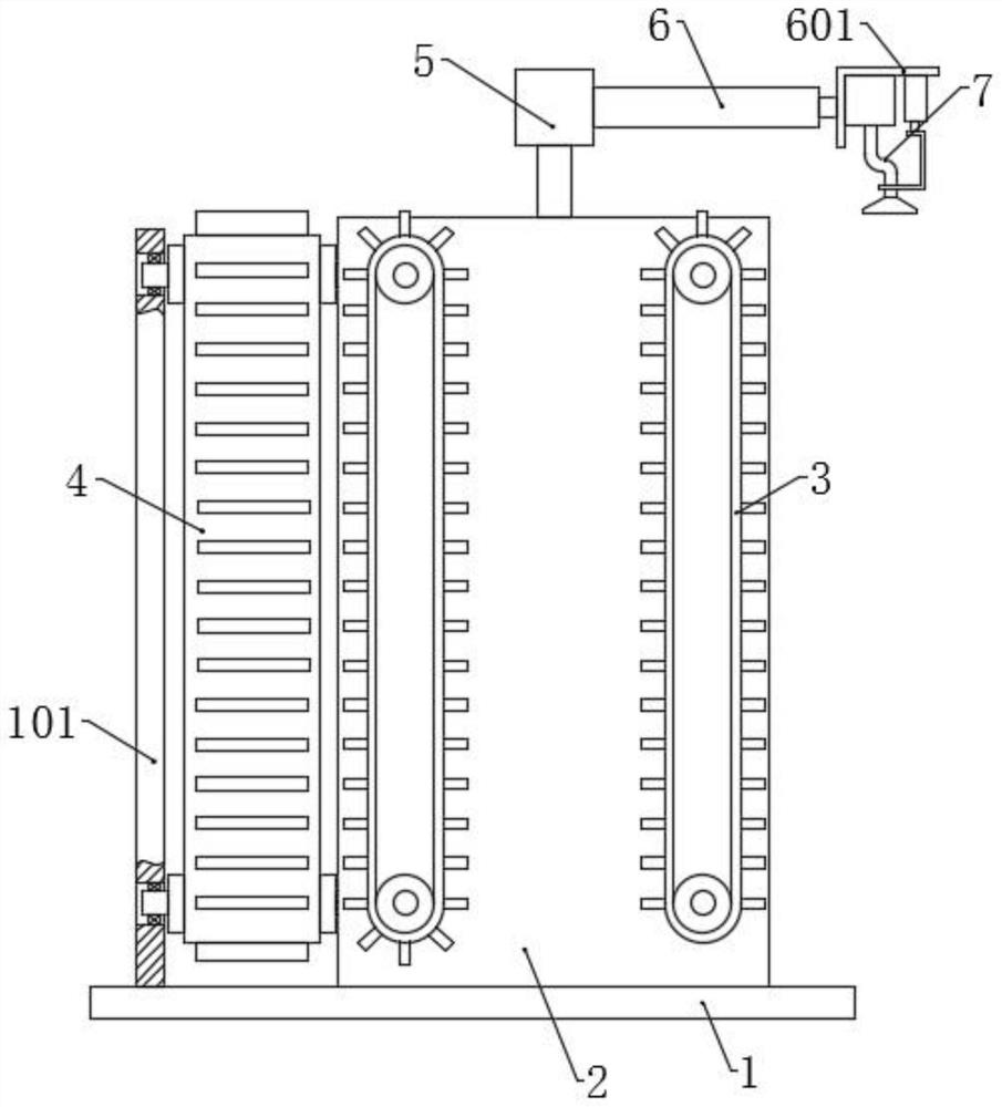
[0030] Please refer to the accompanying drawings, the present invention provides a technical solution: a plate heat exchanger plate transfer rack, including a base 1, a fixed box 2 is fixed on the top surface of the base 1, and a lower The material mechanism 3 is provided with a material feeding mechanism 4 on the rear side, and the top of the fixed box 2 is provided with a rotating assembly 5, and three first hydraulic telescopic rods 6 are fixed on the rotating assembly 5, and the three first hydraulic telescopic rods 6 are successively spaced apart. 90°, the output end of the first hydraulic telescopic rod 6 is fixed with a moving frame 601 , and a fixed component 7 is arranged on the moving frame 601 .
[0031] The working principle of this embodiment is: a processing device is respectively arranged on the right side and the front side of the fixed box 2, and then the plates are moved up intermittently through the feeding mechanism 4, and then the plates are fixed by the fi...
Embodiment 2
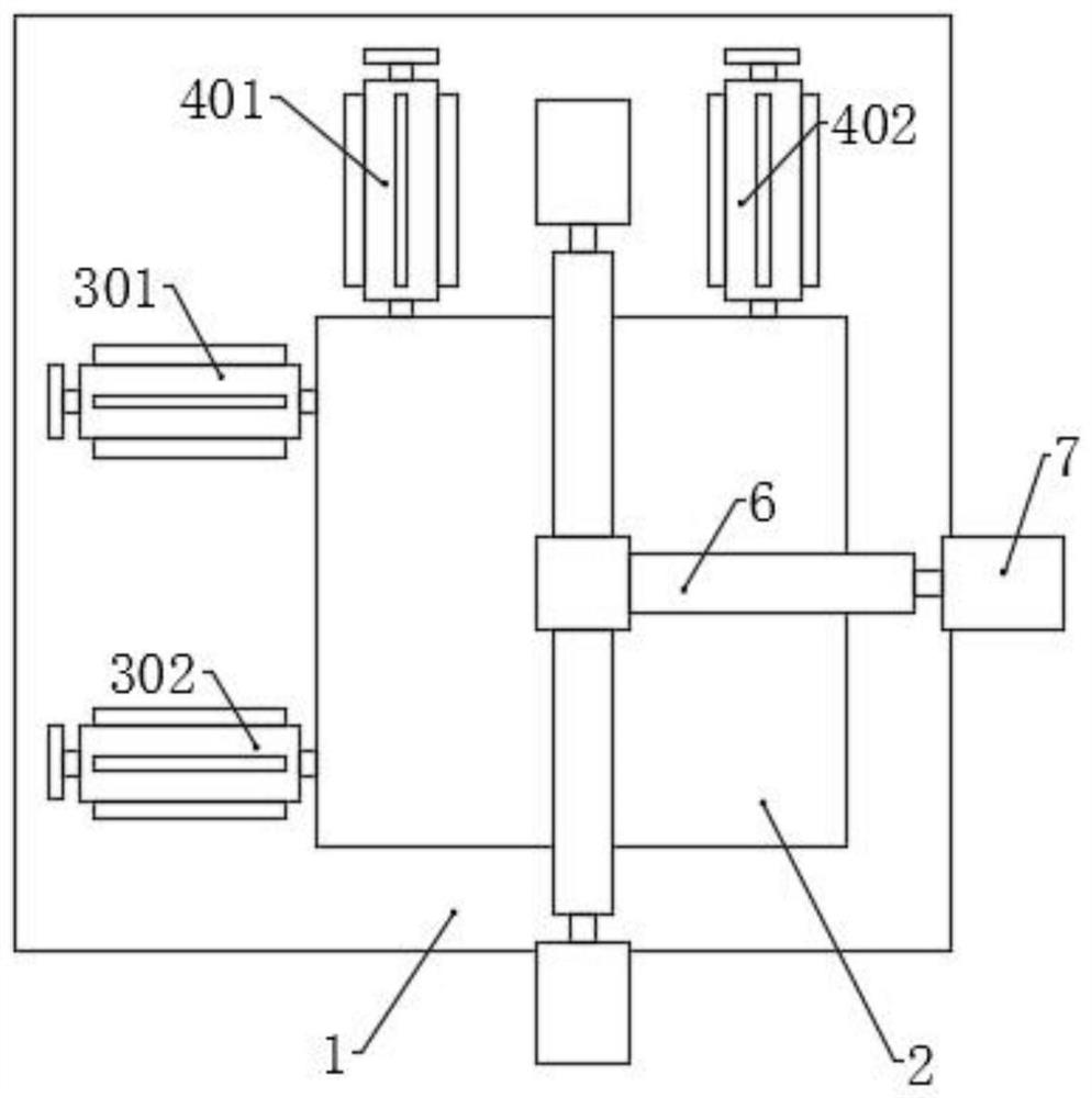
[0033] On the basis of Embodiment 1, the unloading mechanism 3 includes a symmetrically arranged first driving assembly 301 and a first driven assembly 302, and the loading mechanism 4 includes a symmetrically arranged second driving assembly 401 and a second driven assembly 402, And the structure of the first driving assembly 301, the first driven assembly 302, the second driving assembly 401 and the second driven assembly 402 is the same, all including the driving wheel 1002 and the driven wheel 1001, the driven wheel 1001 and the driving wheel 1002 are provided with Conveyor belt 10, conveyor belt 10 is evenly fixed with a plurality of dividers 1005 along the length direction, the center of driving wheel 1002 is fixed with driving shaft 1004, the center of driven wheel 1001 is fixed with driven shaft 1003, and driving shaft 1004 and slave The inner side ends of the moving shaft 1003 are all rotatably connected with the sidewall of the fixed box 2 and extend into the fixed bo...
Embodiment 3
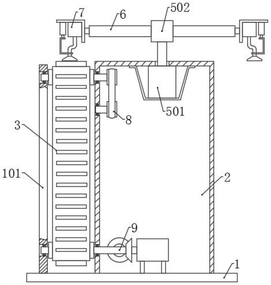
[0039] On the basis of Embodiment 2, the drive assembly 9 includes a drive motor 903 connected to the inner side of the drive shaft 1004 of the first drive assembly 301. The drive motor 903 is electrically connected to a power supply and a switch. On the drive shaft 1004 of the first drive assembly 301 A second bevel gear 902 is also fixed, and a first bevel gear 901 is also fixed on the driving shaft 1004 of the second driving assembly 401 , and the first bevel gear 901 meshes with the second bevel gear 902 .
[0040] The transmission assembly 8 includes a first pulley 801 fixed on two driven shafts 1003, and two transmission gears 803 meshing with each other are arranged symmetrically below the middle of the two first pulleys 801, and the two transmission gears 803 are fixed to each other. The side walls of the box 2 are rotatably connected and coaxially fixed with a second pulley 802, and the two second pulleys 802 are respectively connected to the second pulley 802 on the c...
PUM
 Abstract
Description
Claims
Application Information
 - R&D
- Intellectual Property
- Life Sciences
- Materials
- Tech Scout
- Unparalleled Data Quality
- Higher Quality Content
- 60% Fewer Hallucinations
Browse by: Latest US Patents, China's latest patents, Technical Efficacy Thesaurus, Application Domain, Technology Topic, Popular Technical Reports.
© 2025 PatSnap. All rights reserved.Legal|Privacy policy|Modern Slavery Act Transparency Statement|Sitemap|About US| Contact US: help@patsnap.com