Thread sweeping device of electronic pattern sewing machine

A pattern machine and electronic technology, which is applied to thread hooks for sewing machines, sewing machine components, textiles and paper making, etc., can solve the problems of high production cost, difficult control, poor energy saving, etc., and achieves convenient assembly and maintenance, small space occupation, simplified The effect of the driver

Active Publication Date: 2019-08-02
BULLMER ELECTROMECHANICAL TECH
View PDF6 Cites 0 Cited by
  • Summary
  • Abstract
  • Description
  • Claims
  • Application Information

AI Technical Summary

Problems solved by technology

The head of the electronic pattern machine is usually equipped with a thread sweeping device to pull the thread and prevent the accumulation and winding of the suture. The traditional thread sweeping device uses an electromagnet to push the thread sweeping crank, and then drives the thread sweeping lever to rotate to complete the thread sweeping action. It has the following four problems: 1. The electromagnet is driven, and the stability is poor; 2. The electromagnet needs a separate power line to provide electric energy to realize the action, and the energy saving is poor; 3. It is difficult to control the action angle of the sweeping rod directly; 4. The thread sweeping device has too many components, high production cost, difficult assembly and maintenance
[0004] The thread sweeping device in the above patent documents uses a cylinder to drive the thread sweeping hook, but there are still problems such as many parts, an additional power source is required, and it is difficult to control.

Method used


Image

  • Thread sweeping device of electronic pattern sewing machine
  • Thread sweeping device of electronic pattern sewing machine

Examples


Embodiment Construction

[0023] The following are specific embodiments of the present invention and in conjunction with the accompanying drawings, the technical solutions of the present invention are further described, but the present invention is not limited to these embodiments.

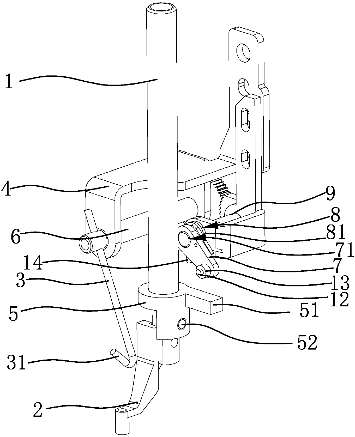
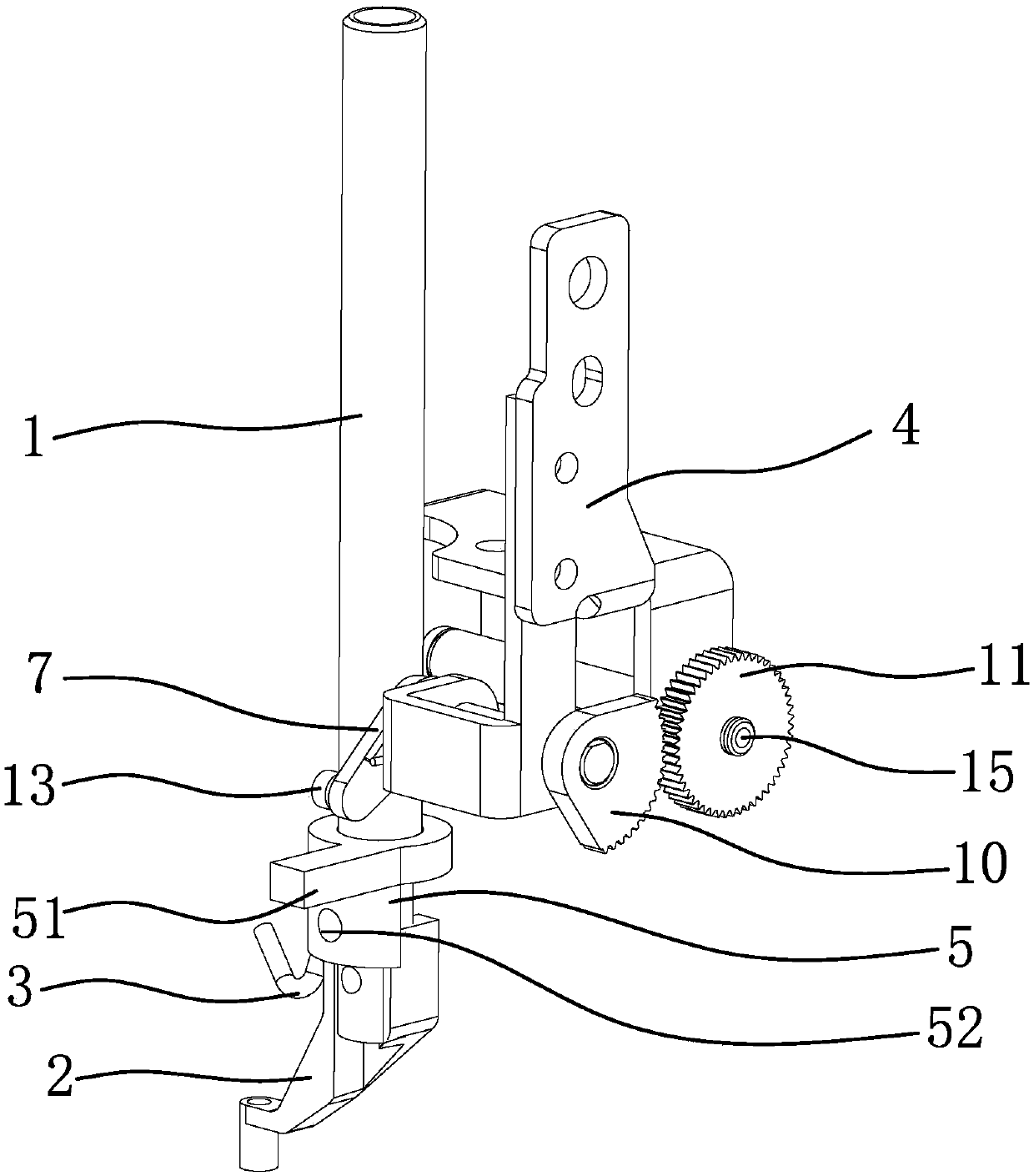
[0024] like figure 1 and figure 2 As shown, the electronic pattern machine includes a presser foot bar 1 capable of reciprocating up and down and a presser foot 2 arranged at the lower end of the presser foot bar 1 , and the thread sweeping device includes a thread sweeper bar 3 , a mounting frame 4 and a presser foot bar fixed on the presser foot bar 1 . The lifting block 5 is provided with a rotating shaft 6 and a swing arm 7 that can drive the rotating shaft 6 to reciprocate on the mounting frame 4. The swing arm 7 is located above the lifting block 5. 7 are in contact with each other and drive it to swing, one end of the thread sweeping rod 3 is connected to the rotating shaft 6, and the other end of the thread sweep...


PUM


Abstract

The invention provides a thread sweeping device of an electronic pattern sewing machine and belongs to the technical field of clothing manufacturing equipment. The thread sweeping device of the electronic pattern sewing machine solves the technical problems that the existing thread sweeping device of the electronic pattern sewing machine has a complex structure and is not easy to control. The electronic pattern sewing machine comprises a pressing foot rod capable of performing reciprocating movement up and down as well as a pressing foot arranged at the lower end of the pressing foot rod; thethread sweeping device comprises a thread sweeping rod, a mounting frame and a lifting block fixedly arranged on the pressing foot rod; a rotating shaft and a swing arm capable of driving the rotatingshaft to perform reciprocating rotation are arranged on the mounting frame; the swing arm is positioned above the lifting block; when the lifting block moves upwards along the pressing foot rod, thelifting block can be contacted with the swing arm and can drive the swing arm to swing, and one end of the thread sweeping rod is connected with the rotating shaft and the other end of the thread sweeping rod stretches to the position of the pressing foot; and an elastic reset piece enabling the rotating shaft to reset is arranged on the mounting frame. The thread sweeping device provided by the invention is simple in structure, accurate in control and low in use cost.

Description

technical field [0001] The invention belongs to the technical field of garment manufacturing equipment, and relates to an electronic pattern machine, in particular to a thread sweeping device of the electronic pattern machine. Background technique [0002] The electronic pattern machine is a machine used by contemporary handbag factories, shoe factories, luggage factories, garment factories, leather goods factories, and furniture factories. Meet the requirements of "multi-level, multi-functional, unity and perfection". It is an electromechanical product that embodies a variety of high-tech. The head of the electronic pattern machine is usually equipped with a thread sweeping device to pull the thread and prevent the accumulation and winding of the suture. The traditional thread sweeping device uses an electromagnet to push the thread sweeping crank, and then drives the thread sweeping lever to rotate to complete the thread sweeping action. It has the following four problem...

Claims


Application Information

Patent Timeline
Patent Type & Authority Applications(China)
IPC IPC(8): D05B53/00
CPCD05B53/00D05D2209/08
Inventor 刘明耀王俊跃刘翔
Owner BULLMER ELECTROMECHANICAL TECH
Why Eureka
Try Eureka