
Concrete pouring device and operating method for road construction

A technology for concrete and roads, applied in roads, buildings, roads, etc., can solve problems such as extended construction period, inner walls covered with concrete, and untimely cleaning of pouring devices, so as to improve the quality of road surfaces, improve construction efficiency, and achieve good cleaning effects

Active Publication Date: 2021-10-08
HARBIN VOCATIONAL & TECHN COLLEGE
View PDF0 Cites 0 Cited by
  • Summary
  • Abstract
  • Description
  • Claims
  • Application Information

AI Technical Summary

Problems solved by technology

Before the concrete is cut into the mold, it is necessary to mix the concrete with a mixer truck and transport the concrete to the construction site. During the transportation, the mixed concrete is prone to problems such as solidification and segregation, which will affect the normal use of the concrete and cause The construction period is extended, and the quality of the concrete pavement cannot be guaranteed
[0003] At the same time, after the pouring is completed, if the pouring device is not cleaned in time, it is easy to cause the inner wall of the pouring device to be covered with concrete, and the discharge port is easy to solidify and accumulate too much concrete over time, which will affect the next use of the pouring device

Method used


Image

  • Concrete pouring device and operating method for road construction
  • Concrete pouring device and operating method for road construction
  • Concrete pouring device and operating method for road construction

Examples


specific Embodiment approach 1

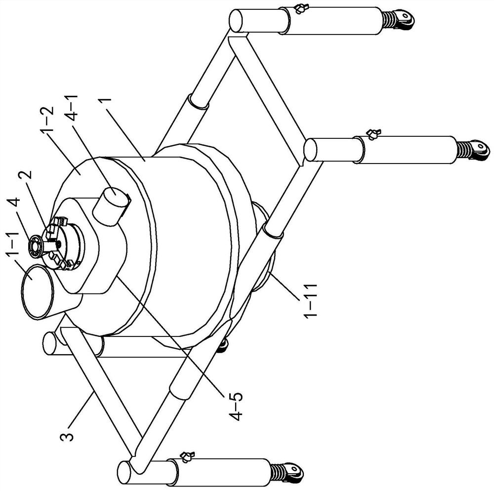
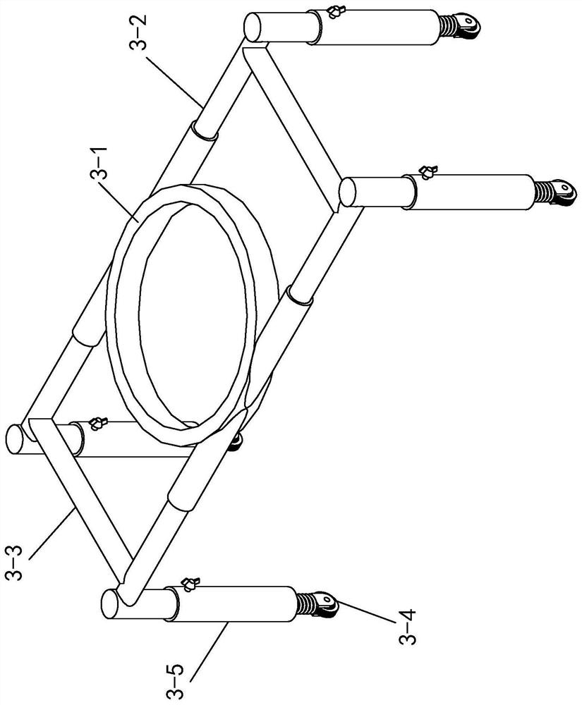
[0026] Specific implementation mode one: as Figure 1 to Figure 7 As shown, the present invention discloses a concrete pouring device for road construction, including a pouring bucket 1, a three-jaw chuck 2, a retractable walking frame 3, a stirring mechanism 4 and a scrubbing mechanism 5;

[0027] The lower end surface of the pouring bucket 1 is provided with a discharge port 1-1, and the discharge port 1-1 is slidably provided with a sealing cover 1-11 (the lower end surface of the discharge port 1-1 is provided with a chute 1-12, the upper end surface of the sealing cover 1-11 is provided with a slider 1-13, the slider 1-13 on the sealing cover 1-11 and the chute 1-12 on the discharge port 1-1 Sliding connection), the sealing cover 1-11 is provided with a handle, the upper end of the pouring bucket 1 is equipped with a bucket cover 1-2, and the bucket cover 1-2 is provided with a feed port 1-21, the The middle part of the bung 1-2 is axially equipped with a stirring mechan...

specific Embodiment approach 2

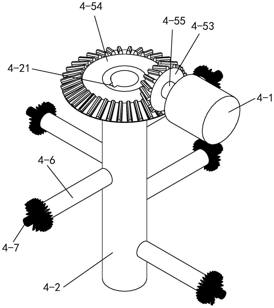
[0028] Specific implementation mode two: as figure 1 , image 3 , Figure 4 , Figure 5 As shown, the stirring mechanism 4 includes a motor 4-1, a shaft tube 4-2, a transition rod 4-3, a shaft sleeve 4-4, a gear box 4-5 and a stirring rod 4-6;

[0029] The disc body of the three-jaw chuck 2 is fixed on the gear box 4-5, and the claws of the three-jaw chuck 2 are used to clamp the outer wall of the bushing 4-4, and the upper end of the bushing 4-4 With a handle 4-41, the inner wall of the shaft sleeve 4-4 is rotationally connected with the upper end of the output shaft 4-51 of the gear box 4-5 through a bearing 4-8, and the output shaft of the gear box 4-5 The lower end of the rod 4-51 is fixedly connected to the upper end of the transition rod 4-3, the output shaft of the motor 4-1 is fixedly connected to the input shaft rod 4-55 of the gear box 4-5, and the shell of the motor 4-1 The body is fixed on the upper end surface of the bucket cover 1-2 through the motor frame, a...

specific Embodiment approach 3

[0030] Specific implementation mode three: as figure 1 , image 3 , Figure 4 As shown, the gearbox 4-5 includes a box body, an output shaft 4-51, a driving bevel gear 4-53, a driven bevel gear 4-54 and an input shaft 4-55;

[0031] The lower end surface of the box body is fixed on the upper end surface of the bucket cover 1-2, the output shaft of the motor 4-1 is fixedly connected with one end of the input shaft rod 4-55, and the motor 4-1 is powered by the outside. The input shaft 4-55 penetrates into the side wall of the box through the rotation of the bearing assembly and is fixedly connected with the middle part of the driving bevel gear 4-53. The bearing assembly includes the second bearing and the bearing seat, and the bearing seat is fixed on the On the inner bottom surface, the driving bevel gear 4-53 meshes with the driven bevel gear 4-54, the driven bevel gear 4-54 is fixed on the outer wall of the shaft tube 4-2, and the shaft tube 4- 2 is rotationally connected...


PUM


Abstract

A concrete pouring device for road construction and an operation method thereof belong to the technical field of concrete pouring equipment. The lower end surface of the pouring barrel is provided with a discharge port, and a sealing cover is slid at the discharge port. The upper end of the pouring barrel is equipped with a cap, and the cap is provided with a feed port. The middle part of the cap is equipped with a stirring mechanism along the axial direction. , the upper end of the stirring mechanism passes through the barrel cover and is fixedly connected with the three-jaw chuck, the three-jaw chuck is fixed on the stirring mechanism, the lower end of the stirring mechanism is equipped with a scrubbing mechanism, and the outer wall of the pouring barrel is fixedly connected with the retractable walking frame; The invention can continuously stir the concrete in the pouring device, avoid the occurrence of solidification or segregation of the concrete in the pouring device, ensure the normal use of the concrete, reduce the construction period, and ensure the quality of the concrete road surface. At the same time, there is a washing mechanism inside to automatically wash The inner wall of the pouring barrel can avoid excessive concrete adhering to the inner wall of the pouring barrel and the discharge port, which will affect the discharge of the discharge port.

Description

technical field [0001] The invention relates to a construction concrete pouring device and an operation method, belonging to the technical field of concrete pouring equipment. Background technique [0002] With the rapid development of the economy, the rapid increase of traffic volume, and the demand for people's travel convenience, it is required to improve the quality of road construction and at the same time shorten the construction period as much as possible, so as to reduce the impact on people's travel. Before the concrete is cut into the mold, it is necessary to mix the concrete with a mixer truck and transport the concrete to the construction site. During the transportation, the mixed concrete is prone to problems such as solidification and segregation, which will affect the normal use of the concrete and cause The construction period was extended, and the quality of the concrete pavement was not guaranteed. [0003] At the same time, if the pouring device is not cl...

Claims


Application Information

Patent Timeline
Patent Type & Authority Patents(China)
IPC IPC(8): E01C19/47
CPCE01C19/47E01C19/475
Inventor 王天成李维维李晓琳李昂杨晓东葛贝德杜丽敏赵光楠王希伟李晓光刘任峰吴岩曹高菲曹洋王福学秦环兵
Owner HARBIN VOCATIONAL & TECHN COLLEGE
Learn More