Wall dismantling device

A wall and mounting plate technology, applied in building maintenance, construction, building construction, etc., can solve the problems of personal injury, difficulty in improving the efficiency of wall demolition, high labor cost, etc., to improve efficiency, easy operation, and improve demolition The effect of efficiency

Active Publication Date: 2019-08-02
HUNAN INST OF TECH
View PDF9 Cites 13 Cited by
  • Summary
  • Abstract
  • Description
  • Claims
  • Application Information

AI Technical Summary

Problems solved by technology

When rebuilding or demolishing a building, manpower is required to remove the wall. Due to the structure of the wall, workers need to repeatedly hammer the wall with a sledgehammer. It is always difficult to improve the efficiency of wall removal, and manual removal of the wall is easy. Injuries to people and high labor costs to manually remove walls

Method used


Image

  • Wall dismantling device
  • Wall dismantling device
  • Wall dismantling device

Examples


Embodiment 1

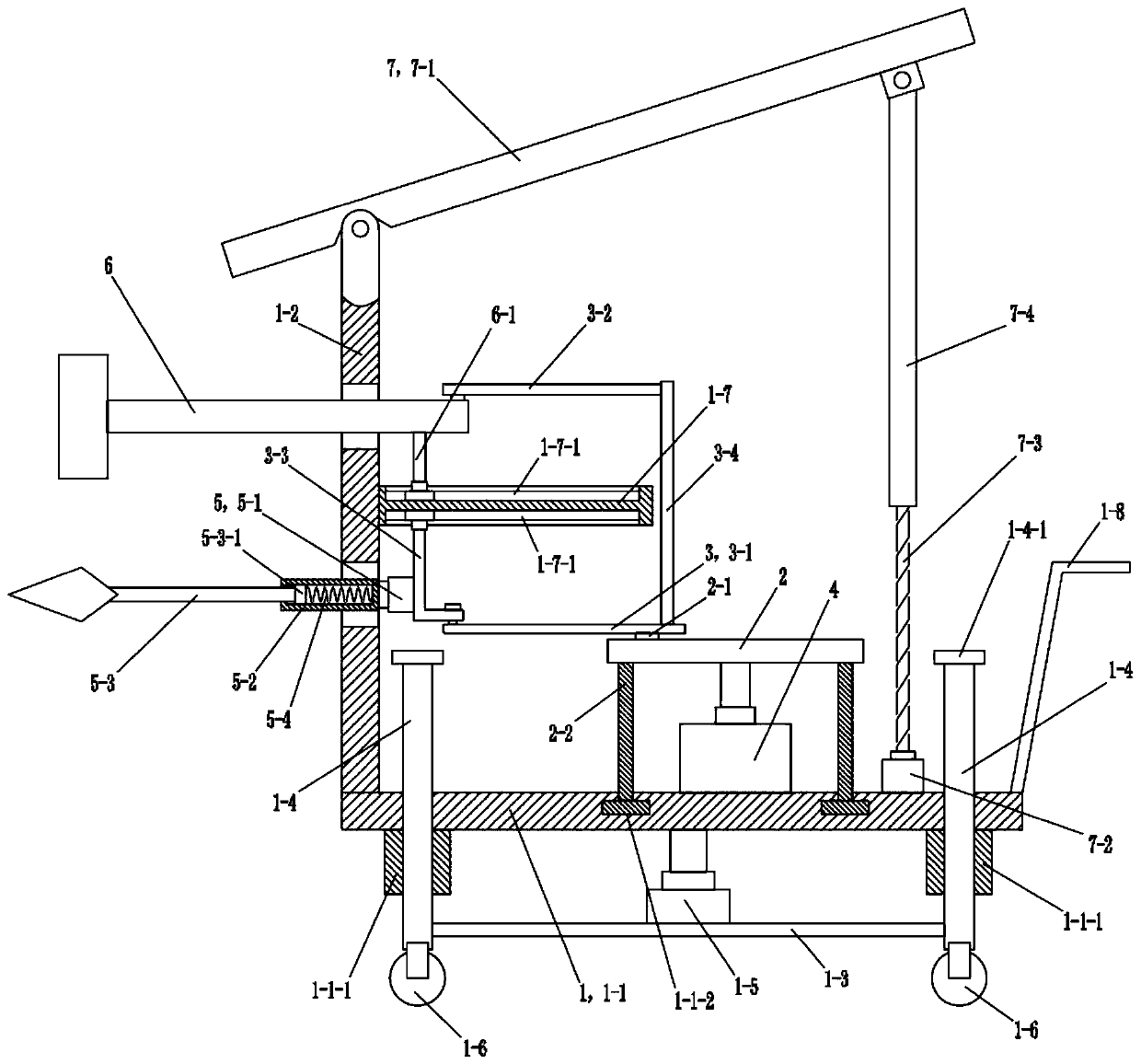
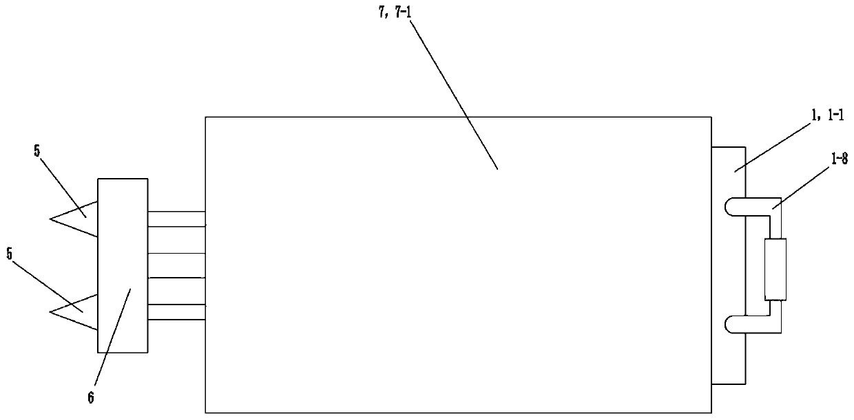
[0030] See figure 1 and figure 2 , The wall removal device of this embodiment includes a vehicle frame 1 , a drive plate 2 , a linkage frame 3 , a drive motor 4 , a drill assembly 5 , an impact hammer 6 and a baffle assembly 7 . Both the drill assembly 5 and the impact hammer 6 are located at the front of the vehicle frame 1 . The driving motor 4 is arranged on the vehicle frame 1 , and the driving shaft of the driving motor 4 is connected with the driving plate 2 . The driving disc 2 is rotatably connected with the linkage frame 3 . The linkage frame 3 is connected with the drill bit assembly 5 and the rear end of the percussion hammer 6 . The baffle assembly 7 includes a baffle 7-1 and a jacking assembly. The baffle plate 7-1 is located above the vehicle frame 1. The jacking assembly drives the rear portion of the baffle plate 7-1 to move upward.

[0031] The vehicle frame 1 includes a chassis 1-1, a mounting plate 1-2, a base plate 1-3, a column 1-4 and a lifting cyl...

Embodiment 2

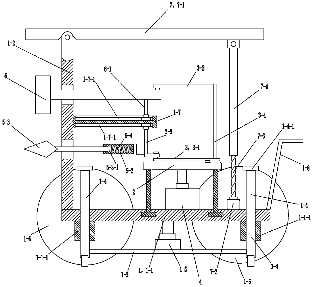
[0041] See image 3 , this embodiment is basically the same as Embodiment 1, the difference is:

[0042] The front portion of the chassis 1-1 of the vehicle frame 1 is provided with wheels 1-6. The radius value of the wheel 1-6 is greater than the minimum distance value between the bottom end of the column 1-4 and the chassis 1-1.

[0043] During use, the lifting cylinder 1-5 drives the chassis 1-1 to move upward, so that each column 1-4 extends downward to support the ground, and the wheels 1-6 are suspended in the air.


PUM


Abstract

The invention discloses a wall dismantling device which comprises a vehicle frame, a driving disc, a linkage frame, a driving motor, a drill bit assembly, an impact hammer and a baffle assembly. The drill bit assembly and the impact hammer are arranged at the front part of the frame, the driving motor is arranged on the frame, and a driving shaft of the driving motor is connected with the drivingdisc; the driving disc is rotationally connected with the linkage frame; the linkage frame is connected with the drill bit assembly and the rear end of the impact hammer; the baffle assembly comprisesa baffle and a jacking assembly; the baffle is arranged above the frame; and the jacking assembly drives the rear portion of the baffle to move upwards. The wall dismantling device is ingenious in structure, the driving disc rotates to drive the drill bit assembly and the impact hammer to do linear reciprocating motion through the linkage frame, when the impact hammer hammers a wall, the drill bit assembly drills the wall surface to damage the structure of the wall surface, the wall surface dismantling efficiency is greatly improved, operation is convenient, the baffle assembly can effectively prevent bricks and concrete of the wall from falling off to damage the internal structure of the device, the service life is prolonged, and the safety is improved.

Description

technical field [0001] The invention relates to the technical field of construction, in particular to a wall removal device. Background technique [0002] Walls are an important part of buildings. Its function is to bear weight, enclose or separate space. The wall is divided into load-bearing wall and non-load-bearing wall according to the force and material of the wall, and divided into solid wall, sintered hollow brick wall, hollow wall and composite wall according to the wall structure. When rebuilding or demolishing a building, manpower is required to remove the wall. Due to the structure of the wall, workers need to repeatedly hammer the wall with a sledgehammer. It is always difficult to improve the efficiency of wall removal, and manual removal of the wall is easy. People are injured, and the labor cost of manually removing walls is high. Contents of the invention [0003] The purpose of the present invention is to provide a wall removal device with high working ...

Claims


Application Information

Patent Timeline
Patent Type & Authority Applications(China)
IPC IPC(8): E04G23/08
CPCE04G23/08
Inventor 牛美玲王本强
Owner HUNAN INST OF TECH
Why Eureka
Try Eureka