Electronic locking device

An electronic lock and self-locking technology, applied in electric locks, vehicle locks, building locks, etc., can solve the concept and goal of restricting the development and design of the vehicle platform, the mismatch between the structure of the locking device and the charging interface, and waste of society Labor and other issues, to avoid the interference of parts in the car body, to solve the tight layout space, and to achieve the effect of small size

Pending Publication Date: 2019-08-02
宁波均胜新能源汽车技术有限公司 +1
View PDF0 Cites 8 Cited by
  • Summary
  • Abstract
  • Description
  • Claims
  • Application Information

AI Technical Summary

Problems solved by technology

Usually, the traditional mechanical lock has complex structure and low reliability. Some lock bodies need to borrow other equipment on the car body to realize the locking function, and the structure of the locking device does not match the charging interface. It needs to be matched with a conversion device. Universal, bulky It is also relatively large, and the manufacturing cost is high, which to a certain extent limits the concept and goal of vehicle platform development and design, directly and indirectly wasting social labor

Method used


Image

  • Electronic locking device
  • Electronic locking device
  • Electronic locking device

Examples


Embodiment Construction

[0032] The technical solutions provided by the present invention will be described in detail below in conjunction with specific examples. It should be understood that the following specific embodiments are only used to illustrate the present invention and are not intended to limit the scope of the present invention.

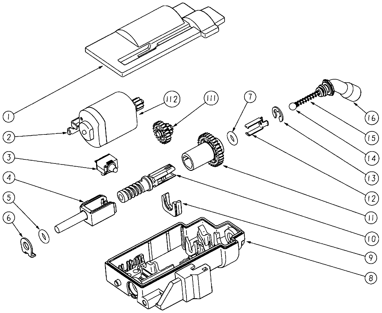
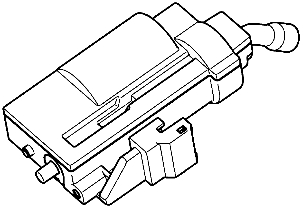
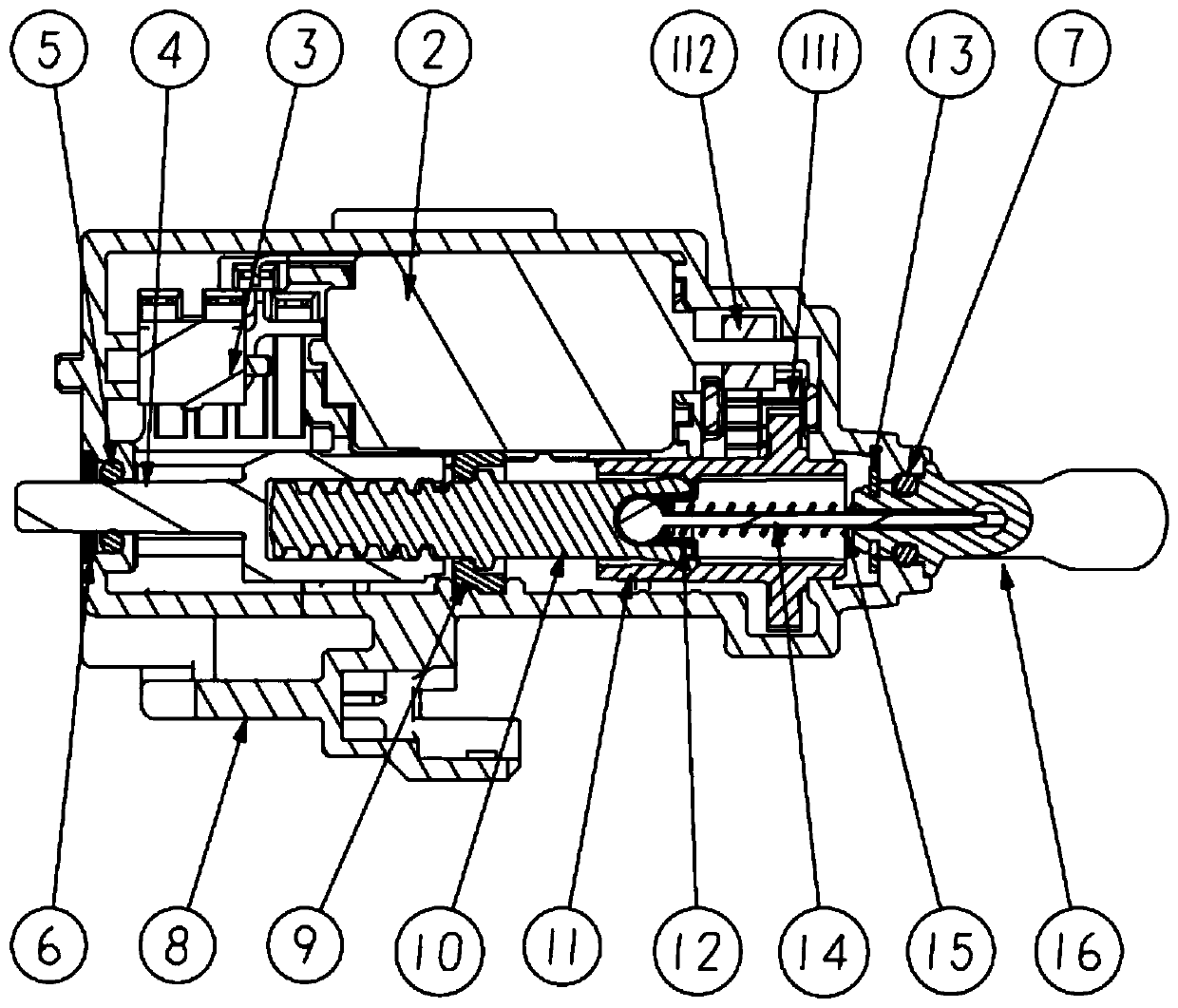
[0033] Such as Figure 1-Figure 6 The electronic locking device shown includes a housing composed of an upper cover 1 and a bottom case 8. In this example, the upper cover 1 and the bottom case 8 are positioned by no less than one flange structure, and rigid Connection, for example, sealant connection, ultrasonic welding, etc.; according to needs, other methods can also be used for connection, and even an integrated structure of the upper cover and the bottom shell can be used. A cavity is formed between the upper cover 1 and the bottom case 8, and the cavity is provided with an electric conversion unit 2, a transmission mechanism, a deadbolt slider 4, a feed scr...


PUM


Abstract

The invention discloses an electronic locking device. The electronic locking device comprises a shell, a power mechanism arranged in the shell, a transmission mechanism, a spring bolt sliding block, afeeding screw rod, a self-locking elastic piece, a reset mechanism and an unlocking action mechanism, wherein the power mechanism, the transmission mechanism, the spring bolt sliding block, the feeding screw rod, the self-locking elastic piece, the reset mechanism and the unlocking action mechanism are arranged in the shell. A locking mechanism provided by the invention is ingenious in concept, the transmission mechanism is ingenious in matching, the safety in a normal state is high, manual unlocking can be effectively prevented, and when emergency manual unlocking is needed, the transmissionmechanism of the electronic locking device can be safely and reliably unlocked; the electronic locking device is high in process integration level, higher in process automation degree, low in cost and higher in protection grade, compared with an former similar product, the structure is simple, the appearance size is small, the cost is low, and a high protection grade can be met; according to theelectronic locking device, the problems that a spring bolt is easily pulled out and the manual unlocking operation is partially followed are solved, and the system misjudgment probability in the charging and locking process is reduced, and the problem that manual unlocking mechanism with internal parts of an automobile body is interfered due to the rotation of an operation handle at the tail end of the manual unlocking mechanism when electric locking and unlocking at each time is avoided.

Description

technical field [0001] The invention belongs to the technical field of charging equipment for new energy vehicles, and relates to a locking device used for charging interfaces of new energy vehicles. Background technique [0002] With the rapid development of electric vehicle charging technology, there are more and more types of vehicle charging sockets, and the charging speed is getting faster and faster. At present, the vehicle charging interface locking devices that exist to improve the safety of the charging process are collectively referred to as electronic locks. Electronic locks are divided into mechanical lock cylinders and electromagnetic lock cylinders. Usually, the traditional mechanical lock has complex structure and low reliability. Some lock bodies need to borrow other equipment on the car body to realize the locking function, and the structure of the locking device does not match the charging interface. It needs to be matched with a conversion device. Univers...

Claims


Application Information

Patent Timeline
Patent Type & Authority Applications(China)
IPC IPC(8): E05B83/28E05B81/06E05B79/10E05B79/20E05B85/00
CPCE05B79/10E05B79/20E05B81/06E05B83/28E05B85/00
Inventor 赵斯聪刘玉达朱恺史汝海王随亚王志伟
Owner 宁波均胜新能源汽车技术有限公司
Why Eureka
Try Eureka