
Small gangway bridge hydraulic system

A hydraulic system and step bridge technology, applied in the field of step bridges, can solve problems such as unstable operation of step bridges, and achieve the effects of improving work stability, oil pressure stability, and precise roll compensation.

Active Publication Date: 2019-08-02
SOUTH CHINA MARINE MACHINERY
View PDF9 Cites 2 Cited by
  • Summary
  • Abstract
  • Description
  • Claims
  • Application Information

AI Technical Summary

Problems solved by technology

In addition, due to the control system and hydraulic system, the work of the step bridge is unstable.

Method used


Image

  • Small gangway bridge hydraulic system
  • Small gangway bridge hydraulic system
  • Small gangway bridge hydraulic system

Examples


Embodiment Construction

[0047] The present invention will be further described in detail below in conjunction with the accompanying drawings and specific embodiments.

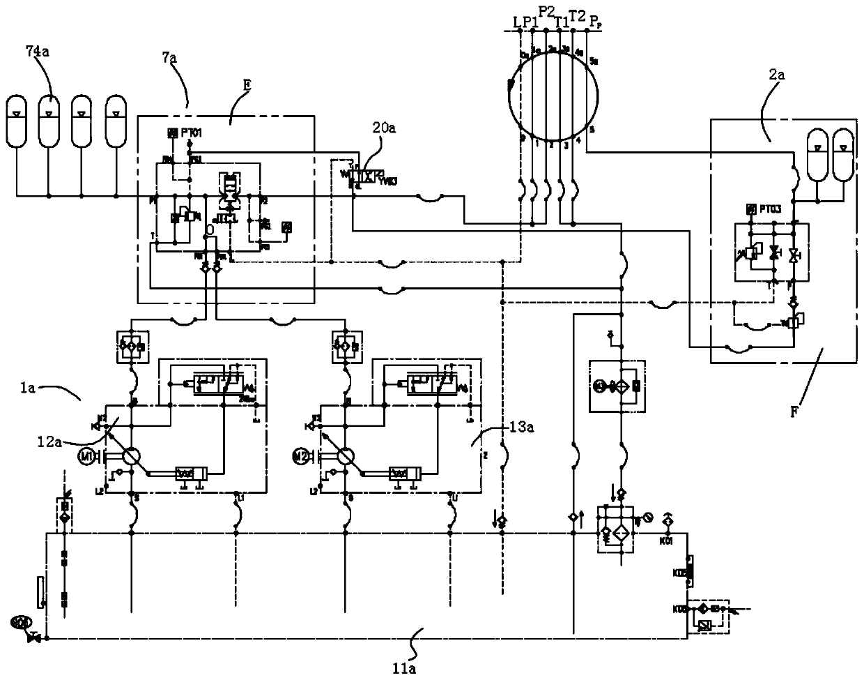
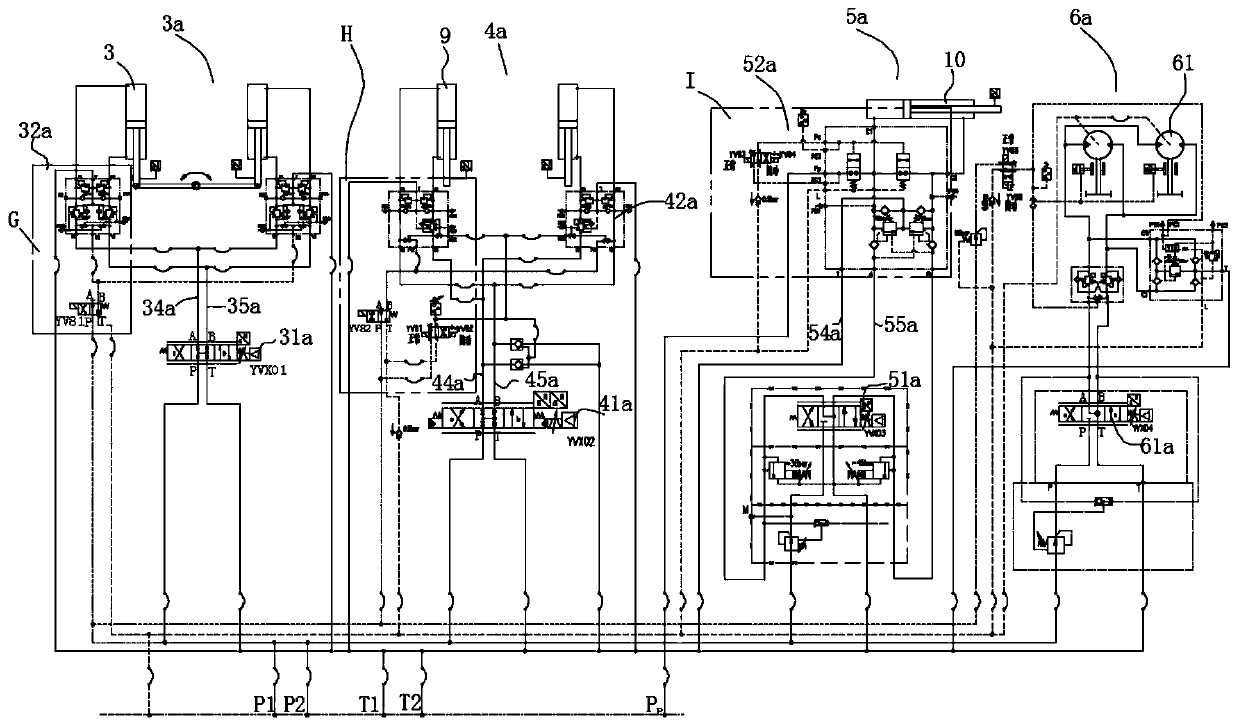
[0048] Such as figure 1 and figure 2 As shown, the small step bridge hydraulic system includes a main oil supply system 1a, a constant thrust accumulator system 2a, a roll compensation system 3a, a pitch compensation system 4a, a telescopic system 5a and a slewing system 6a.

[0049] The main oil supply system 1a includes a fuel tank 11a, a first hydraulic pump 12a and a second hydraulic pump 13a connected to the fuel tank 11a; the first hydraulic pump 12a is driven by a motor M1, and the second hydraulic pump 13a is driven by a motor M2; the first hydraulic pump 12a is driven by a motor M2; The output terminals of the pump 12a and the second hydraulic pump 13a are collected to form a total output terminal O.

[0050] After the motor M1 and the motor M2 are started, the first hydraulic pump 12a and the second hydraulic pump 13a are...


PUM


Abstract

The invention discloses a small gangway bridge hydraulic system. The small gangway bridge hydraulic system comprises a main oil supplying system, a constant thrust energy accumulator system, a transverse rocking compensating system, a pitching compensating system, a telescopic system and a rotating system. Due to the system, better following and compensating can be achieved through the hydraulic system, and overlap joint of a gangway bridge is reliable, safe and efficient.

Description

technical field [0001] The present invention relates to walkways. Background technique [0002] The step bridge or trestle bridge is mainly used to transport people or goods. On land, the construction of the step bridge is relatively simple, but it is relatively difficult to build the step bridge used to transport people and materials between two ships at sea. Because the boats move with each other, the step bridge is generally built on a ship. If it needs to be used, the step bridge is set between the two ships by lapping. In the lapping process, in order to achieve a better lap, it is necessary to consider the relative position between the bridge and another ship, otherwise the bridge and the ship will collide due to the floating of the ship; after the lap is completed, It is also necessary to consider the relative position between the two ships. According to the relative position of the two ships, the step bridge is in a state of passive compensation, so that normal use ...

Claims


Application Information

Patent Timeline
Patent Type & Authority Applications(China)
IPC IPC(8): F15B11/17F15B1/04F15B13/02F15B13/06B63B27/30
CPCB63B27/30F15B1/04F15B11/17F15B13/026F15B13/06
Inventor 陈懿李新献梁兆环王江安万平
Owner SOUTH CHINA MARINE MACHINERY
Learn More