
Fluid magnetic vector support applied to hydraulic element

A technology of hydraulic components and magnetic vectors, applied in the field of friction pairs, can solve problems such as wear of friction pairs in hydraulic components, achieve the effects of improving support rigidity, improving efficiency and service life, and ensuring sealing effect

Active Publication Date: 2019-08-02
HARBIN INST OF TECH
View PDF4 Cites 3 Cited by
  • Summary
  • Abstract
  • Description
  • Claims
  • Application Information

AI Technical Summary

Problems solved by technology

[0005] The purpose of the present invention is to solve the wear problem of the friction pair in the hydraulic element, and then provide a liquid magnetic vector support applied to the hydraulic element

Method used


Image

  • Fluid magnetic vector support applied to hydraulic element

Examples


Embodiment 1

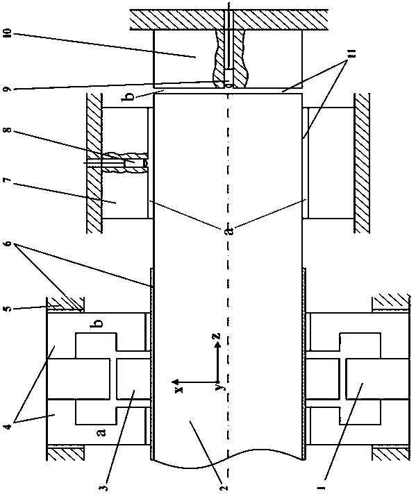
[0017] Embodiment one: if figure 1 As shown, a liquid magnetic vector support applied to hydraulic components involved in this embodiment includes a radial magnetic force unit, a friction pair moving coupler, an iron core, an axial magnetic force unit, a housing, a magnetic isolation material, a radial The static coupling of the friction pair, the radial displacement sensor, the axial displacement sensor, the stationary coupling of the axial friction pair, the moving coupling of the friction pair, the stationary coupling of the radial friction pair and the stationary coupling of the axial friction pair exist High-pressure liquid film, the friction pair motion couple has been driven to have linear motion or rotational motion along the z-axis, the radial inner surface of the radial magnetic force unit is directly opposite to the radial outer surface of the iron core, and the iron core and the radial The distance between the magnetic units is set to form a radial working gap. The...

Embodiment 2

[0019] Embodiment two: if figure 1 As shown, this embodiment involves a liquid magnetic vector support applied to hydraulic components. The magnetic support structure of the present invention is used to realize the vector support for the friction pair of hydraulic components. It adopts a combined magnetic unit design, The radial magnetic unit and the axial magnetic unit can be matched and combined according to the radial or axial relative motion relationship between the friction pair, and the position information of the friction pair motion detected by the radial displacement sensor and the axial displacement sensor Adjusting the magnetic field of the axial magnetic force unit and the radial magnetic force unit can set the initial gap between the friction pair moving part and the friction pair stationary part. With the formation of the high-pressure liquid film, by adjusting the axial magnetic force unit and the radial magnetic force The magnetic force generated by each part o...


PUM


Abstract

The invention provides a fluid magnetic vector support applied to a hydraulic element, and belongs to the field of friction pair coupling parts in hydraulic elements. According to the fluid magnetic vector support applied to the hydraulic element, closed-loop control is further carried out over the thickness of a high-pressure fluid film by adjusting the magnetic force of axial magnetic force units and a radial magnetic force unit, a friction pair can be prevented from being worn, meanwhile, oil leaking is reduced to the greatest degree, the efficiency of the hydraulic element is improved, andthe service life of the hydraulic element is prolonged. An iron core is mounted on the side face of a friction pair motion coupling part, the radial magnetic force unit is arranged at the position right facing the iron core, the axial magnetic force units are symmetrically arranged on the two sides of the radial magnetic force unit, and a magnetic force unit set is formed jointly. A radial displacement sensor and an axial displacement sensor are mounted on a radial friction pair static coupling part and an axial friction pair static coupling part correspondingly and are used for monitoring the thickness of the high-pressure fluid film, the change information of the high-pressure fluid film is fed back to the radial magnetic force unit and the axial magnetic force units, a magnetic field generated by the high-pressure fluid film is weakened or reinforced, and the thickness of the high-pressure fluid film is kept within the ideal range.

Description

technical field [0001] The invention relates to a liquid magnetic vector support applied to hydraulic components, which belongs to the field of friction pairs in hydraulic components. Background technique [0002] The friction pair is a key part of hydraulic components, usually composed of stationary parts and moving parts with a certain movement law, and the high-pressure liquid film between the friction pairs has a certain bearing and sealing effect. According to its working principle, the moving parts are usually subjected to axial or radial dynamic loads. Due to the limited rigidity of the high-pressure liquid film, additional support torque and support force are required between the friction pair parts, resulting in wear on the surface of the friction pair. This phenomenon occurs in Hydraulic components using low-viscosity media are more serious. [0003] It can be seen that the existing friction pairs of hydraulic components inevitably wear out, resulting in a certain...

Claims


Application Information

Patent Timeline
IPC IPC(8): F16C32/04
CPCF16C32/0402
Inventor 姜继海杜博然张彪胡志栋
Owner HARBIN INST OF TECH
Learn More