
Butterfly valve of intermediate-pressure cylinder of steam turbine

A technology of steam turbine and medium pressure cylinder, which is applied in the field of butterfly valve of steam turbine medium pressure cylinder, can solve the problems of occupying additional space, high investment, complex system, etc., and achieves the effect of saving land occupation and investment.

Pending Publication Date: 2019-08-02
GUODIAN SCI & TECH RES INST
View PDF5 Cites 3 Cited by
  • Summary
  • Abstract
  • Description
  • Claims
  • Application Information

AI Technical Summary

Problems solved by technology

In this modification method, the butterfly valve of the medium-pressure cylinder of the steam turbine is completely closed or the minimum flow limit opening of the disc is reduced, so that the passing steam flow is smaller or zero, and the steam inlet flow is adjusted by the added bypass. This modification method requires Add some equipment such as pipelines, throttling parts and regulating valves, the system is complex, the investment is high, and additional space is occupied

Method used


Image

  • Butterfly valve of intermediate-pressure cylinder of steam turbine
  • Butterfly valve of intermediate-pressure cylinder of steam turbine
  • Butterfly valve of intermediate-pressure cylinder of steam turbine

Examples


Embodiment 1

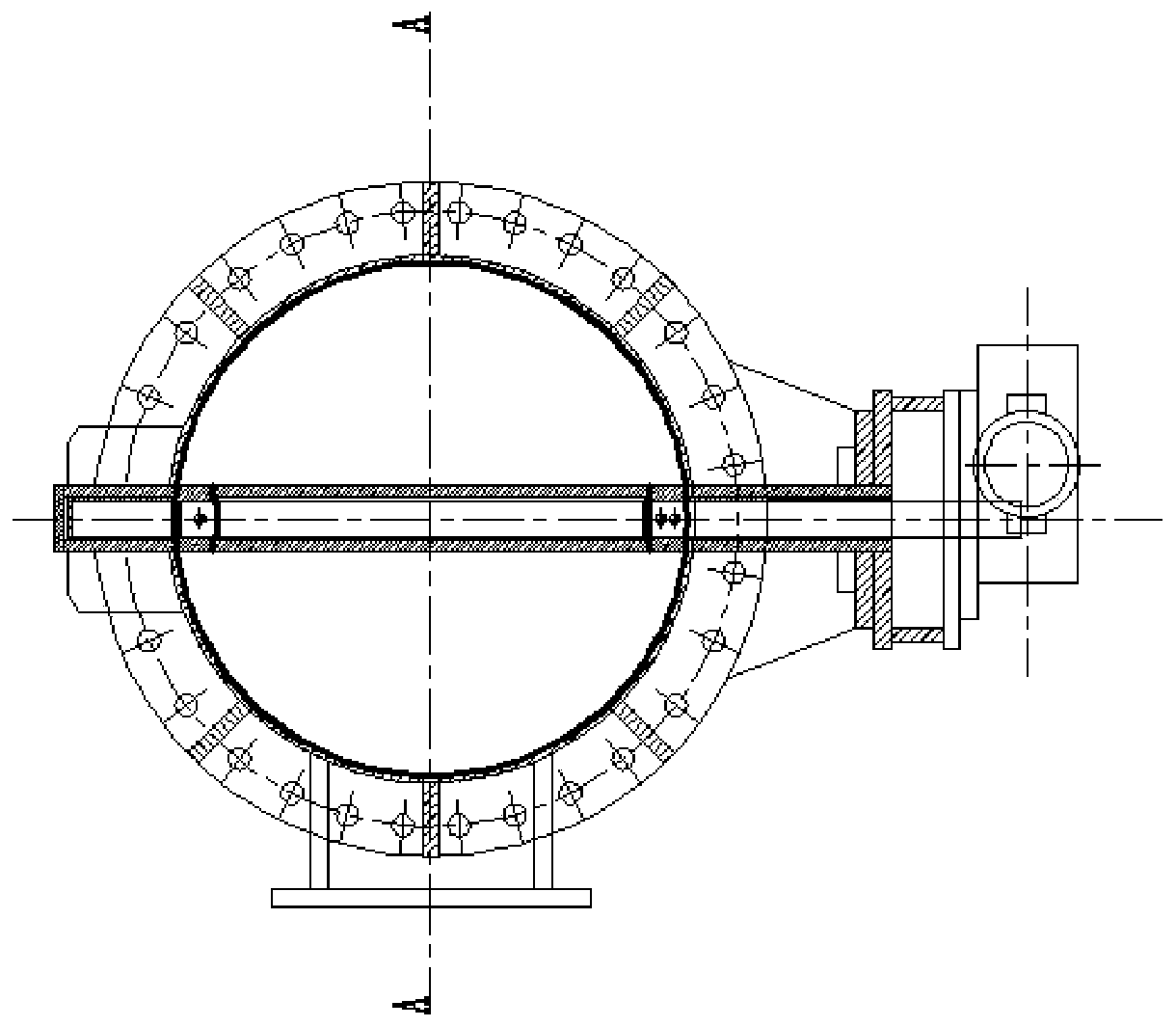
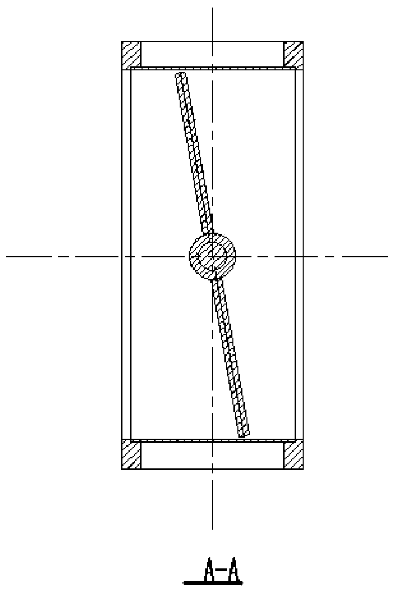
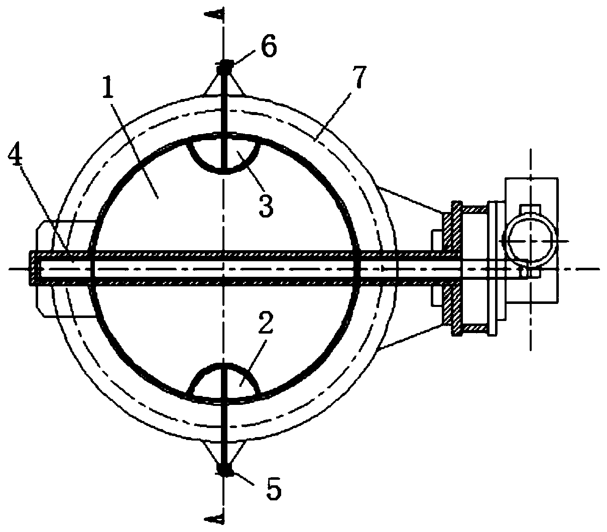
[0028] like image 3 and Figure 4 As shown, the butterfly valve of the steam turbine medium pressure cylinder of the present invention includes a valve body, a rotating shaft and an electric actuator for driving the rotating shaft, and is also provided with a valve disc 1 adapted to the outlet of the medium pressure cylinder. The valve disc 1 is installed through the rotating shaft 4 On the valve body at the outlet of the medium pressure cylinder, two small valve discs are arranged on the sealing surface of the valve disc 1, which are respectively the small valve disc 2 and the small valve disc 3. The sealing surface means that when both the valve disc and the small valve disc are closed, they are in a plane and close the section of the medium pressure cylinder.

[0029] The two small discs are installed symmetrically on both sides of the rotating shaft, and the rotating shafts of the two small discs are set perpendicular to the rotating shaft of the butterfly valve. The val...

Embodiment 2

[0032] Optionally, in this example, a small valve disc inscribed with the valve disc is installed at both ends of the rotating shaft of the butterfly valve disc in the medium-pressure cylinder of the steam turbine. The rotating shaft of the valve disc is perpendicular to the axis of the small disc. Turn on to adjust the intake steam flow into the low-pressure cylinder to meet and maintain the minimum flow for the safe operation of the low-pressure cylinder. For ease of installation and adjustment of the inlet steam flow.

[0033] like Figure 5 As shown, the plane shape of the small valve disc is approximately semicircular, and the two ends of the small valve disc in contact with the valve disc should avoid acute angles. The size of the added small disc is determined according to the steam inlet flow rate. 3% to 5% of the disc flow area, the structure of the small disc shaft is the same as that of the butterfly valve.

[0034] The working process is as follows:

[0035] Whe...


PUM


Abstract

The invention provides a butterfly valve of an intermediate-pressure cylinder of a steam turbine. The butterfly valve is used for adjusting the flow of steam entering a low-pressure cylinder. The butterfly valve of the intermediate-pressure cylinder of the steam turbine is arranged on an outlet of the intermediate-pressure cylinder. The butterfly valve mainly comprises a valve body, a valve clack,a rotating shaft and electric execution mechanisms, and is mainly characterized in that two small valve clacks are mounted on the sealing face of the valve clack; gaps matched with the small valve clacks are formed at the positions, corresponding to the mounting positions of the small valve clacks, on the valve clack, and a rotating clearance is reserved; the two small valve clacks are symmetrically mounted at the positions, on the two sides of the rotating shaft of the valve body, and rotating shafts of the two small valve clacks are perpendicular to the rotating shaft and are guided out from the valve body; and the small valve clacks are used for slightly adjusting the steam flow. The butterfly valve can be used for adjusting the quantity of steam entering the low-pressure cylinder, therequirement of safe operating of the low-pressure cylinder can be met, extracted steam is utilized for heat supply to the largest degree, and the advantages of saving occupied land, saving investments and the like are achieved.

Description

technical field [0001] The invention relates to a structure type of a butterfly valve of a medium-pressure cylinder of a steam turbine, which is convenient for adjusting the flow of steam entering the low-pressure cylinder of the steam turbine. Background technique [0002] The heating transformation of thermal power units is an important means to achieve "energy saving and emission reduction". Increasing year by year, unit flexibility transformation work has been carried out one after another. [0003] Before the flexibility transformation of the steam turbine of the thermal power unit, the steam enters the low-pressure cylinder after passing through the high-pressure and medium-pressure cylinders of the steam turbine and the butterfly valve of the medium-pressure cylinder. Part of the steam is used to generate electricity through the generator, and part of the steam enters the exhaust device. There are generally two types of butterfly valves for medium-pressure cylinders ...

Claims


Application Information

Patent Timeline
Patent Type & Authority Applications(China)
IPC IPC(8): F16K1/22F16K1/36F01D17/10
CPCF16K1/223F16K1/36F01D17/10
Inventor 马庆中张晓东曹蓉秀白玉宇石红晖郭爱武陈阳康朝斌张伟
Owner GUODIAN SCI & TECH RES INST
Learn More