Device for measuring blade tip clearance of thin-walled case

A technology of blade tip clearance and measuring device, which is applied in the direction of mechanical clearance measurement, etc., to achieve good operability, reduce the number of openings, and improve work efficiency

Active Publication Date: 2019-08-02
AECC SHENYANG ENGINE RES INST
View PDF11 Cites 8 Cited by
  • Summary
  • Abstract
  • Description
  • Claims
  • Application Information

AI Technical Summary

Problems solved by technology

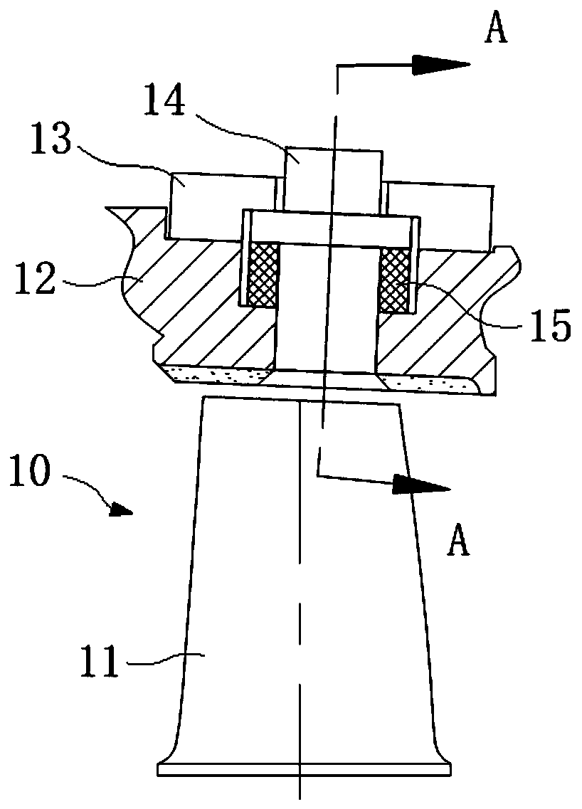
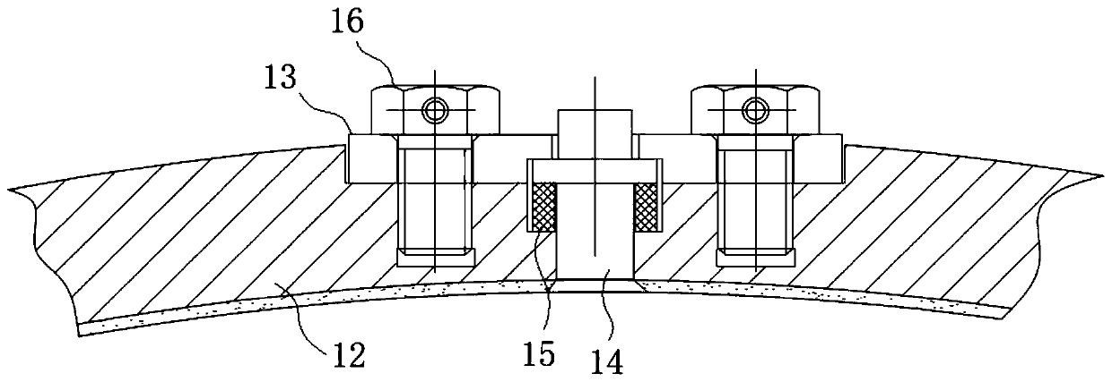
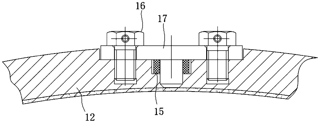
[0005] The purpose of this application is to provide a thin-wall casing tip clearance measuring device to solve or alleviate at least one of the problems in the background art

Method used


Image

  • Device for measuring blade tip clearance of thin-walled case
  • Device for measuring blade tip clearance of thin-walled case
  • Device for measuring blade tip clearance of thin-walled case

Examples


Embodiment Construction

[0028] In order to make the purpose, technical solution and advantages of the application more clear, the technical solution in the embodiment of the application will be described in more detail below in conjunction with the drawings in the embodiment of the application.

[0029] like Figure 4 As shown, the blade tip clearance measuring device 20 applicable to the thin-wall casing of the present application includes a sensor 23, a protective bushing 24, a lead wire branch pipe 26 and a measuring bracket 27, wherein the sensor 23 adopts a capacitive sensor, and the front end of the sensor 23 is installed to protect The bushing 24, the protective bushing 24 fits into the thin-walled casing 22 with a small gap and extends into the thin-walled casing 22, and is used to hold the end of the sensor 23 so that the sensor can measure the tip clearance of the rotor blade 21, and the sensor 23 The rear end is installed on the lead wire branch pipe 26, and the test line or metal wire of ...


PUM


Abstract

The invention relates to a device for measuring a blade tip clearance of a thin-walled case, and belongs to the field of aero-engines. The device comprises a sensor, a protective bush, a lead branch pipe and a measuring support; the front end of the sensor is provided with the protective bush; the protective bush extends into the thin-walled case and is used for the sensor to measure the blade tipclearance of rotor blades; the rear end of the sensor is installed on the lead branch pipe and penetrates out of the lead branch pipe; the protective bush is fixed to the thin-walled case in a pressfit mode through the lead branch pipe; and the lead branch pipe is fixed to a force-bearing case through the measuring support. According to the device for measuring the blade tip clearance of the thin-walled case, the sensor is fixed in the form of the lead branch pipe and the measuring support, so that the number of holes of the thin-walled case is reduced, the structural strength of the thin-walled case is ensured, the phenomenon that the sensor is non-firmly fixed due to excessively small lengths, matched with the case, of bolts is avoided, and the measuring range of the sensor and the reliability of an engine are expanded and improved.

Description

technical field [0001] The application belongs to the technical field of aero-engine testing, and in particular relates to a thin-wall casing blade tip clearance measuring device. Background technique [0002] Aeroengine rotor-stator blade tip dynamic clearance has an important impact on the stability of compressor structure and performance. Reasonable blade tip clearance can reduce the occurrence of engine rotor-stator rubbing and ensure engine safety. Therefore, it is necessary to measure the blade tip during the engine design stage. Clearance provides basic data support for optimizing engine design, improving engine performance and reliability. [0003] Due to the narrow space of the engine and the thin wall of the case, the dynamic gap measurement structure not only needs to take into account the strength, machinability and sealing form of the case, but also ensures the measurement accuracy of the sensor, which is convenient for relevant staff operate. [0004] like F...

Claims


Application Information

Patent Timeline
IPC IPC(8): G01B5/14
CPCG01B5/14
Inventor 夏婷婷吴才广刘冬
Owner AECC SHENYANG ENGINE RES INST
Why Eureka
Try Eureka