Test method and test device for touch panel

A technology of touch panel and test method, which is applied in the direction of measuring device, measuring electricity, measuring electrical variable, etc., can solve the problems of high price of testing machine, complicated principle, and inability to measure the capacitance method.

Active Publication Date: 2019-08-02
KUSN INFOVISION OPTOELECTRONICS
View PDF17 Cites 2 Cited by
  • Summary
  • Abstract
  • Description
  • Claims
  • Application Information

AI Technical Summary

Problems solved by technology

However, the existing test methods such as capacitance method and resistance method have the following problems when testing whether there is a unilateral disconnection o

Method used


Image

  • Test method and test device for touch panel
  • Test method and test device for touch panel
  • Test method and test device for touch panel

Examples


Example Embodiment

[0024] In order to further illustrate the technical means and effects of the present invention to achieve the intended purpose, the following will combine the drawings and preferred embodiments to describe the specific implementations, methods, and steps of the testing method and device for the touch panel proposed in the present invention. , Structure, characteristics and effects, detailed description is as follows.

[0025] The foregoing and other technical contents, features and effects of the present invention will be clearly presented in the following detailed description of the preferred embodiment with reference to the drawings. Through the description of the specific embodiments, the technical means and effects of the present invention to achieve the intended purpose can be understood more deeply and concretely. However, the accompanying drawings are only for reference and explanation, and are not used to describe the present invention. limit.

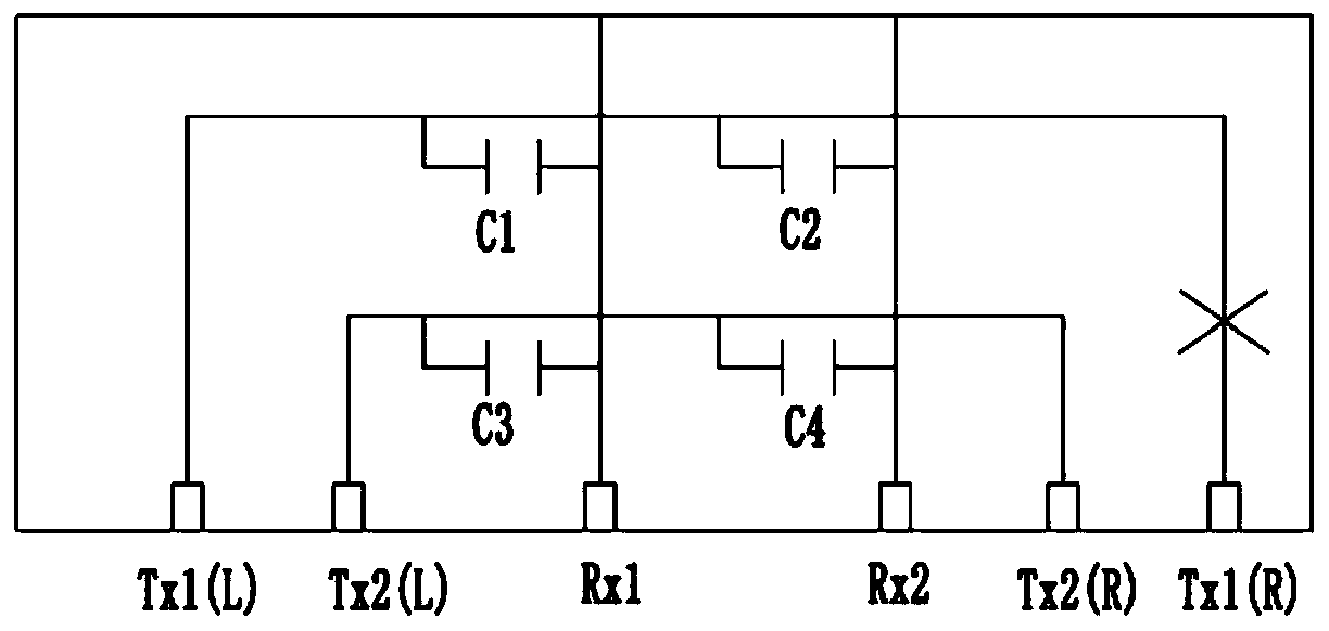
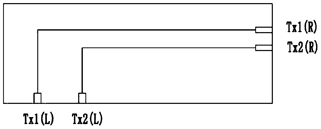
[0026] Figure 4 Is a test ...


PUM


Abstract

The invention provides a test method and a test device for a touch panel. Each driving touch line of the touch panel is driven by two connected driving electrodes, each induction touch line of the touch panel is driven by one connected induction electrode, and the test method of the touch panel comprises the following steps: sending a test signal to at least one induction electrode of the touch panel; whether the two driving electrodes corresponding to the driving touch lines receive the coupling signals or not is tested; if yes, judging whether the driving touch lines are broken or not according to the relationship between the time difference between the time when the two driving electrodes corresponding to the driving touch lines receive the coupling signals and a time threshold value; and if not, determining that the driving touch lines are subjected to routing disconnection. According to the invention, the test signal is sent to at least one sensing electrode of the touch panel, and the time difference of receiving the coupling signal by the two driving electrodes corresponding to the driving touch line is compared, so that whether the driving touch line is broken or not can besimply, quickly and accurately tested.

Description

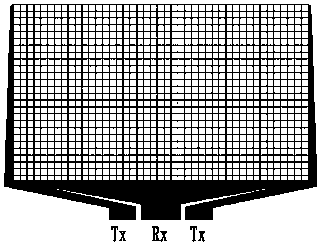
technical field [0001] The invention belongs to the field of display technology, and relates to a test method and a test device for a touch panel. Background technique [0002] figure 1 It is a schematic diagram of wiring connection of an existing on-cell touch panel. Such as figure 1 As shown, the metal grid of the touch panel includes a plurality of driving touch lines along the first direction and a plurality of sensing touch lines along the second direction in the touch area, and any driving touch line of the touch panel The line is driven by two connected driving electrodes, and any sensing touch line is driven by one connected sensing electrode. However, the existing test methods such as capacitance method and resistance method have the following problems when testing whether there is a single-sided disconnection of the touch panel: 1. The principle is complicated and requires high-precision resolution; 2. The capacitance method cannot be measured; 3. The test Mach...

Claims


Application Information

Patent Timeline
IPC IPC(8): G01R31/02
CPCG01R31/50
Inventor 王鹏飞武天竹
Owner KUSN INFOVISION OPTOELECTRONICS
Why Eureka
Try Eureka