Thermal environment analysis method and device, equipment and storage medium
An analysis method and analysis method technology, applied in the field of devices, equipment and storage media, and thermal environment analysis methods, can solve the problems of inaccurate thermal environment analysis, not in line with national conditions, etc., and achieve the effect of accurate results and simple operation.
- Summary
- Abstract
- Description
- Claims
- Application Information
AI Technical Summary
Problems solved by technology
Method used
Image
Examples
Embodiment 1
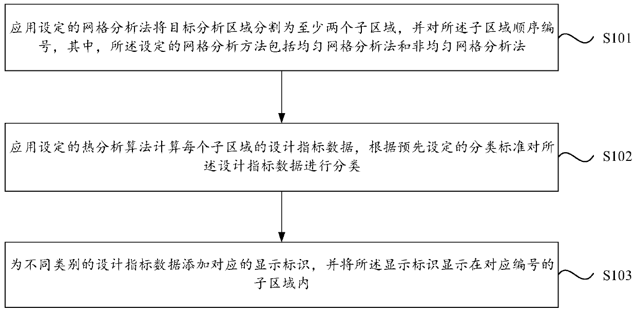
[0037] figure 1 It is a flow chart of a thermal environment analysis method provided by an embodiment of the present invention. The method can be executed by the thermal environment analysis device provided by the embodiment of the present invention, and the device can be implemented in the form of software and / or hardware. refer to figure 1 , the method may specifically include the following steps:
[0038] S101. Apply the set grid analysis method to divide the target analysis area into at least two sub-areas, and sequentially number the sub-areas, wherein the set grid analysis method includes uniform grid analysis method and non-uniform grid analysis method grid analysis.
[0039] Specifically, the set grid analysis method includes a uniform grid analysis method and a non-uniform grid analysis method. Among them, the uniform grid analysis method refers to a calculation area according to the length and width of the minimum grid set in advance. Divide the area with the angl...
Embodiment 2
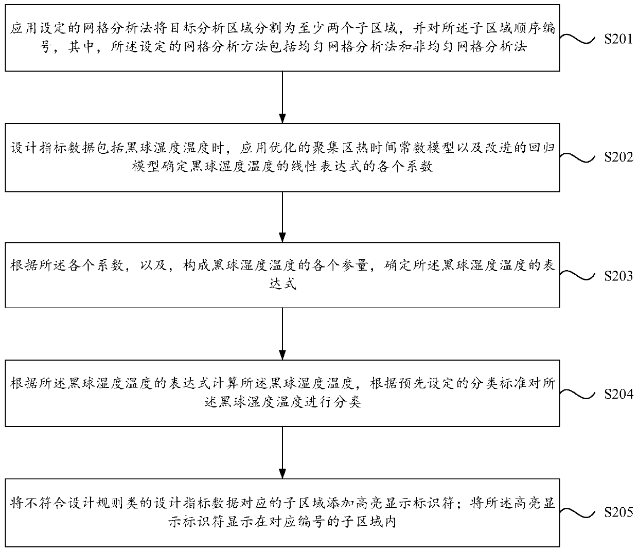
[0059] figure 2 It is a flow chart of another thermal environment analysis method provided by the embodiment of the present invention, and this embodiment is implemented on the basis of the above-mentioned embodiments. refer to figure 2 , the method may specifically include the following steps:
[0060] S201. Apply the set grid analysis method to divide the target analysis area into at least two sub-areas, and sequentially number the sub-areas, wherein the set grid analysis method includes uniform grid analysis method and non-uniform grid analysis method grid analysis.
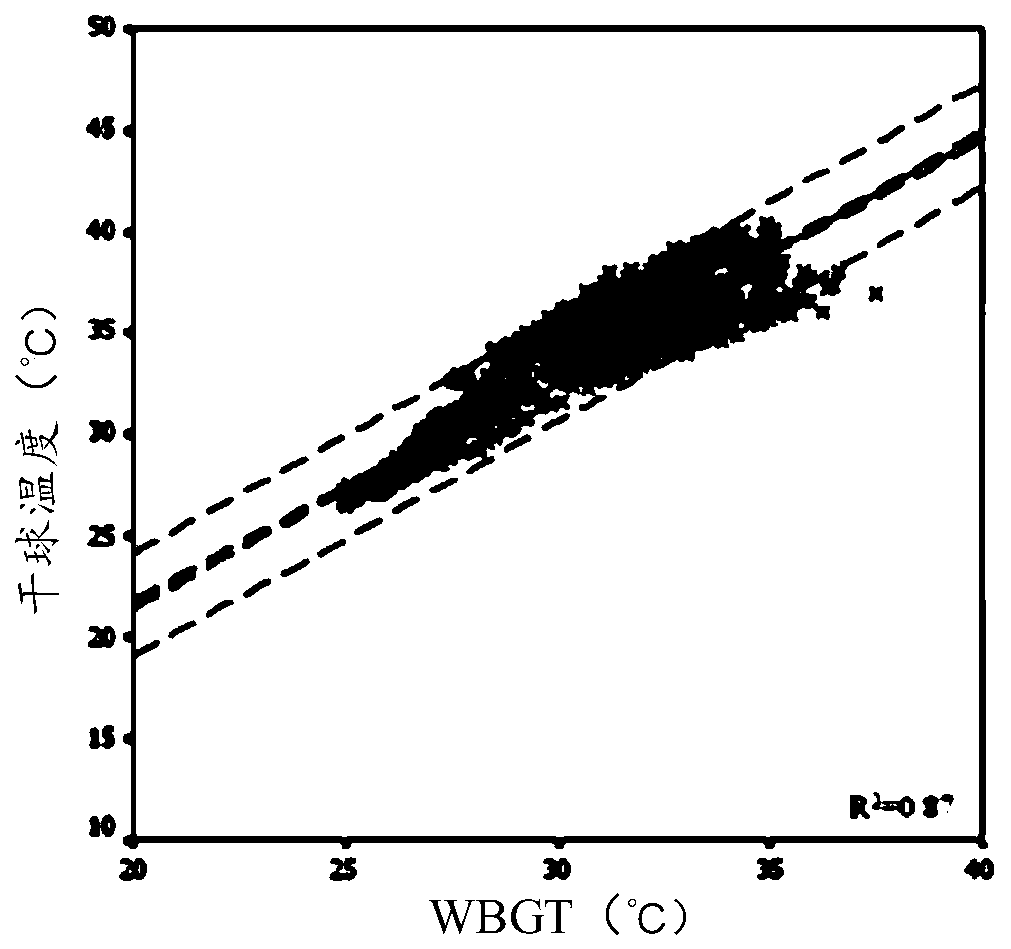
[0061] S202. When the design index data includes the humidity and temperature of the black globe, apply the optimized thermal time constant model of the accumulation area and the improved regression model to determine the coefficients of the linear expression of the humidity and temperature of the black globe.
[0062] Specifically, when the design index data is Wet Bulb Globe Temperature (WBGT), the opti...
Embodiment 3
[0153] Figure 13 It is a schematic structural diagram of a thermal environment analysis device provided in an embodiment of the present invention, which is suitable for performing a thermal environment analysis method provided in an embodiment of the present invention. Such as Figure 12 As shown, the device may specifically include:
[0154] The area segmentation module 1301 is used to divide the target analysis area into at least two sub-areas by using a set grid analysis method, and sequentially number the sub-areas, wherein the set grid analysis method includes a uniform grid analysis method and non-uniform mesh analysis method;
[0155] The data classification module 1302 is used to apply the set thermal analysis algorithm to calculate the design index data of each sub-area, and classify the design index data according to the preset classification standard;
[0156] The display module 1303 is configured to add corresponding display marks to different types of design i...
PUM
 Abstract
Description
Claims
Application Information
 - R&D
- Intellectual Property
- Life Sciences
- Materials
- Tech Scout
- Unparalleled Data Quality
- Higher Quality Content
- 60% Fewer Hallucinations
Browse by: Latest US Patents, China's latest patents, Technical Efficacy Thesaurus, Application Domain, Technology Topic, Popular Technical Reports.
© 2025 PatSnap. All rights reserved.Legal|Privacy policy|Modern Slavery Act Transparency Statement|Sitemap|About US| Contact US: help@patsnap.com


