Relay base cover mounting device

A relay and cover feeding technology, applied in relays, circuits, electrical components, etc., can solve the problems of prone to misalignment, low placement efficiency, and reduced relay base capping efficiency, so as to reduce the probability of misplacement and increase placement efficiency. , the effect of high efficiency

Active Publication Date: 2019-08-02
WENZHOU DRESDNER AUTOMATION TECH CO LTD
View PDF6 Cites 2 Cited by
  • Summary
  • Abstract
  • Description
  • Claims
  • Application Information

AI Technical Summary

Problems solved by technology

[0003] In the production process of the relay base, the general production process is to first produce the corresponding shell, the internal conductive sheet parts and the cover, and then complete the production of the relay base by assembling, and then assemble the conductive terminal parts to the shell After inside, it is necessary to carry out the capping operation at this time, and the cap is sealed on the casing to form a sealed structure, so as to complete the production of the relay base, and the existing caps are generally snap-fitted to ensure airtightness. It is connected to the shell by means of a capping method, so a large force is required to press the cap into the shell during the capping process. Therefore, in the prior art, in order to increase the capping efficiency, the capping machine is basically used to automate the capping process. Sealed on the casing, the existing capping machine includes a conveyor belt and a capping cylinder, the casing with the cap is gradually conveyed to the bottom of the capping cylinder through the conveyor belt, and then the cap is pressed by the capping cylinder It is sealed into the shell, and the cover needs to be manually placed on the shell before the cap is sealed. On the one hand, the placement efficiency is low, and on the other hand, it is easy to be biased during the placement process, which greatly reduces the The capping efficiency of the relay base is improved

Method used


Image

  • Relay base cover mounting device
  • Relay base cover mounting device
  • Relay base cover mounting device

Examples


Embodiment approach

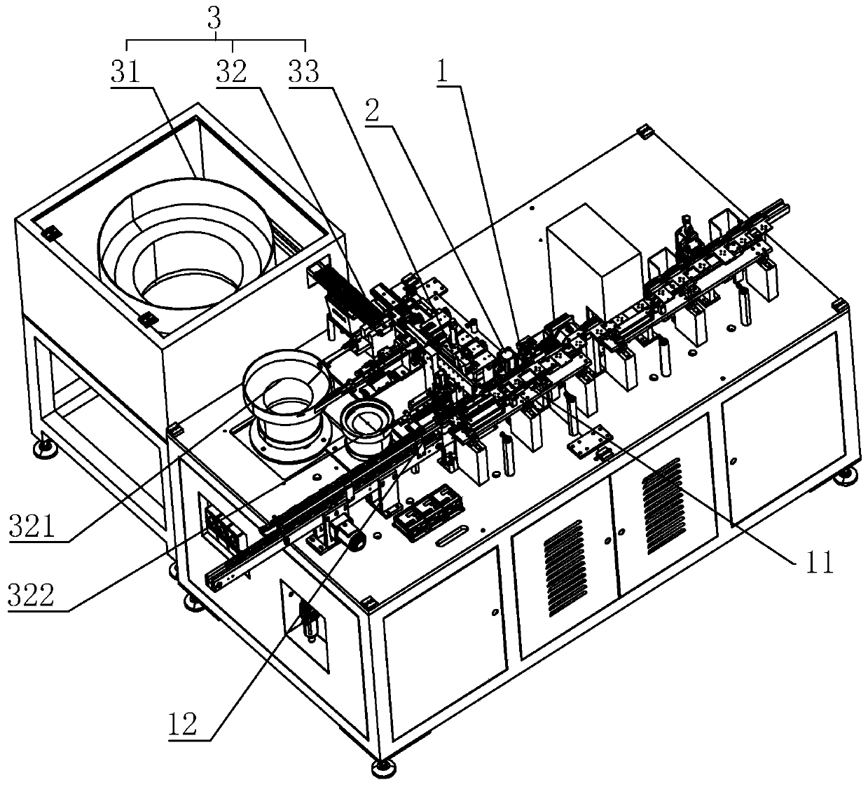
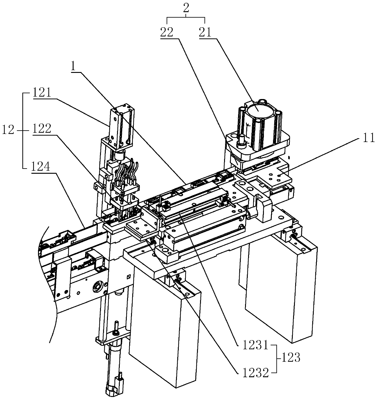
[0028] As an improved specific implementation, the detection and waste discharge mechanism 12 includes a detection cylinder 121, a detection head 122, a waste discharge assembly 123 communicating with the detection head 122, and a waste discharge track 124. One end of the waste discharge track 124 is connected to The ends of the transmission track 1 are connected, the detection cylinder 121 is fixed above the end of the waste discharge track 124 opposite to the transmission track 1, the detection head 122 is fixed on the push rod of the detection cylinder 121, and pushed by the detection cylinder 121, it extends into the Detect the assembled terminals in the casing, and output a signal to the waste discharge assembly 123 when the detection result is unqualified, the waste discharge assembly 123 pushes the current casing into the waste discharge track 124, through the cooperation of the detection head 122 and the detection cylinder 121 function, it can simply and effectively det...


PUM


Abstract

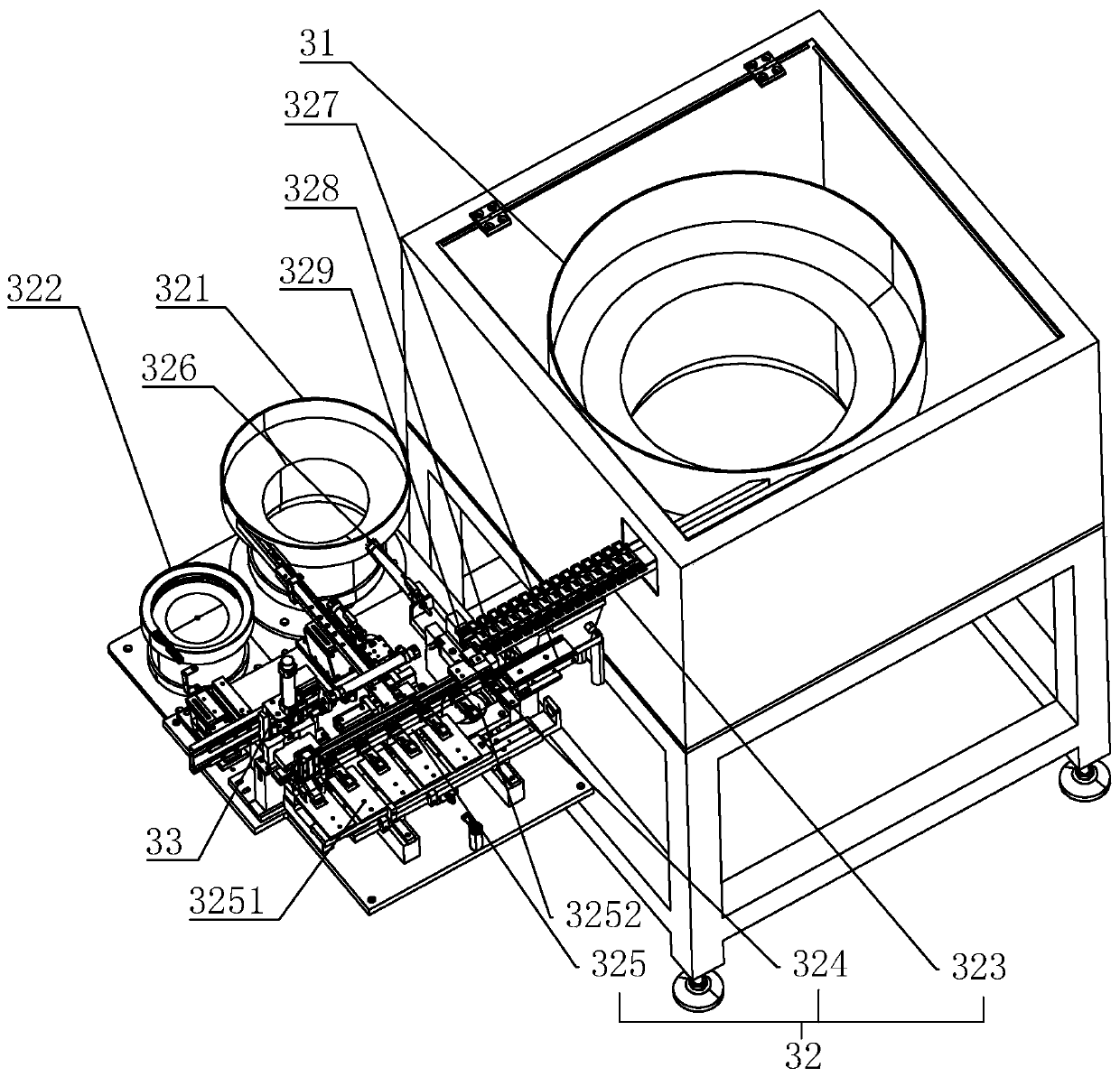
The invention discloses a relay base cover mounting device, which comprises a conveying track, a cover press-fitting device and a cover feeding device, wherein the cover feeding device and the cover press-fitting device are arranged on one side of the conveying track side by side, one end of the conveying track is connected to the previous station, receives a housing assembled at the previous station and gradually passes through the cover feeding device and the cover press-fitting device, the cover feeding device includes a cover feeding vibration disc, a cover feeding track and a cover feeding manipulator, one end of the cover feeding track is connected to the cover feeding vibration disc and receives a cover output by the cover feeding vibration disc, the other end extends to the conveying track, and the cover feeding manipulator is arranged above the end, which is opposite to the conveying track, of the cover feeding track. The relay base cover mounting device disclosed by the invention can effectively realize the automatic feeding of a cover to the housing through the cooperation of the cover feeding vibration disc, the cover feeding track and the cover feeding manipulator.

Description

technical field [0001] The invention relates to a cover device, in particular to a relay base cover device. Background technique [0002] In the process of using the relay, a relay base is generally set up to connect with the external circuit. On the one hand, the multiple connectors required on the relay can be connected in a centralized manner to avoid the problem of cluttered lines. On the other hand, it can It is convenient to replace the relay. [0003] In the production process of the relay base, the general production process is to first produce the corresponding shell, the internal conductive sheet parts and the cover, and then complete the production of the relay base by assembling, and then assemble the conductive terminal parts to the shell After inside, it is necessary to carry out the capping operation at this time, and the cap is sealed on the casing to form a sealed structure, so as to complete the production of the relay base, and the existing caps are gener...

Claims


Application Information

Patent Timeline
Patent Type & Authority Applications(China)
IPC IPC(8): H01H49/00
CPCH01H49/00
Inventor 刘德彬
Owner WENZHOU DRESDNER AUTOMATION TECH CO LTD
Why Eureka
Try Eureka