Reticulated annular deployable antenna and antenna truss

An antenna and ring technology, which is applied in the field of mesh ring expandable antenna and its antenna truss, can solve the problems of difficult to increase the diameter storage ratio, limit the storage ratio, and the structure cannot be completely folded, etc., so as to increase the deployment aperture, height and diameter The effect of storage ratio improvement

Active Publication Date: 2019-08-02
XIDIAN UNIV
View PDF10 Cites 12 Cited by
  • Summary
  • Abstract
  • Description
  • Claims
  • Application Information

AI Technical Summary

Problems solved by technology

[0005] Relevant scholars from Xidian University proposed a W-style deployable antenna scheme. Since the truss adopts an up-and-down asymmetric structure, it has achieved a breakthrough that the folded height is smaller than the unfolded height, but its structure cannot be completely folded to 90 degrees, so the limit storage ratio in the diameter direction
Therefore, although the W-style deployable antenna solution greatly reduces the folding height, when it is used in a mesh deployable antenna, its diameter storage ratio is difficult to increase

Method used


Image

  • Reticulated annular deployable antenna and antenna truss
  • Reticulated annular deployable antenna and antenna truss
  • Reticulated annular deployable antenna and antenna truss

Examples


Embodiment 1

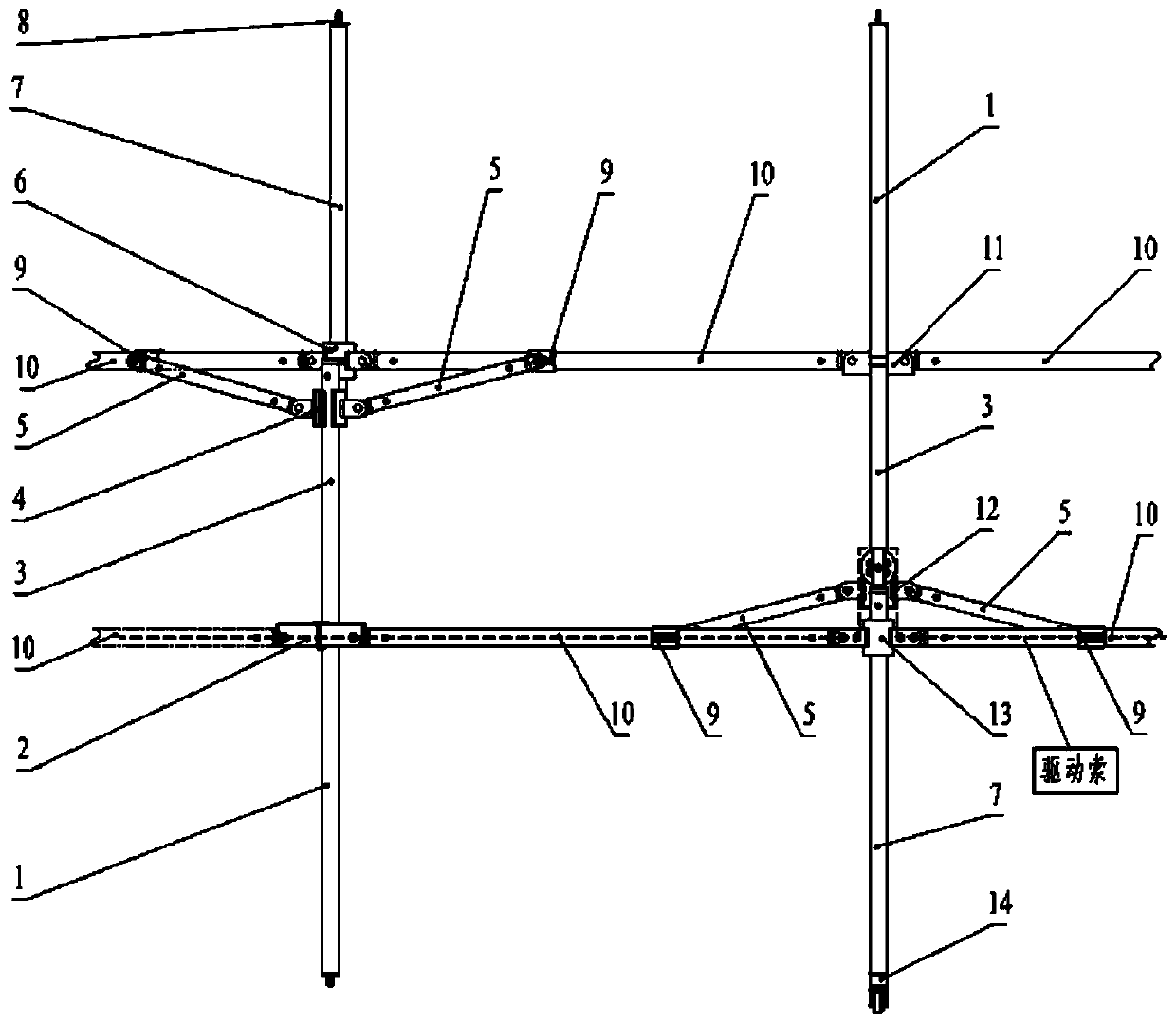
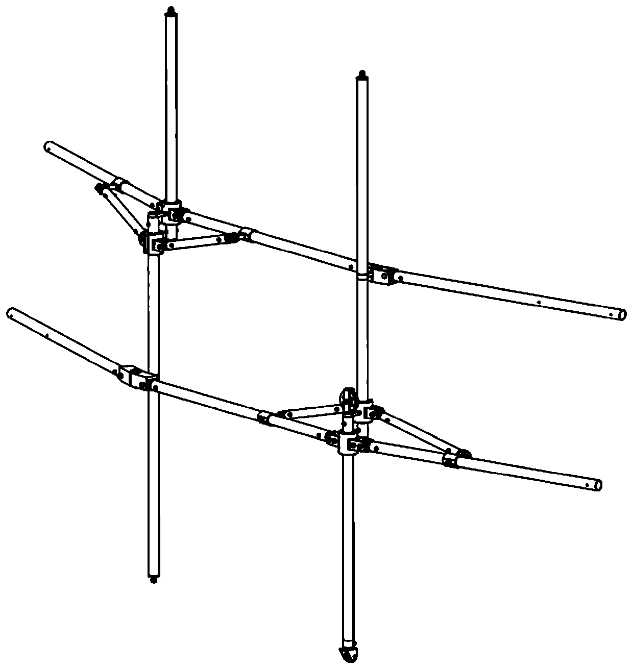
[0056] This embodiment provides a new type of space mesh annular expandable antenna truss structure device, its structure includes a plurality of structural units as shown in Figure 2 (a), and a closed cross bar 10 is formed between adjacent units Ring structure; one of the structural units includes four horizontal bars 10, two sliding vertical bars 7, two main vertical bars 3, two outstretched vertical bars 1, four connecting rods 5, a lower horizontal bar fixed joint 2, One upper link sliding joint 4, one upper cross bar sliding joint 6, one upper cross bar fixed joint 11, one lower link sliding joint 12, one lower cross bar sliding joint 13 and four hinge joints connecting the cross bar and the connecting rod Joint 9.

[0057] The antenna truss adopts a circular hinged expandable mechanism, which is a rigid hinged ring in the expanded state and a cylinder in the folded state. The annular hinged expandable mechanism includes five types of rods, which are horizontal rods 10 ...

Embodiment 2

[0068] In this embodiment, on the basis of Embodiment 1, the mechanism adopts a torsion spring-cable combined driving mode to drive and unfold, that is, a torsion spring is installed at the hinge position of the cross bar 10 and the connecting rod 5; 10, the lower cross bar fixed joint 2, the lower cross bar sliding joint 13, the lower connecting rod sliding joint 12; its specific structure is as follows Figure 6 As shown, one end of the torsion spring 9-3 is fixed on the shaft 9-2 of the hinged joint 9, and the other end is fixed on the inside of the connecting rod connector 9-4. On 9-2, elastic potential energy is stored. As shown in Figure 2(a), the drive cable runs through the interior of the lower cross bar 10, and bypasses the pulleys provided on the lower cross bar fixed joint 2, the lower cross bar sliding joint 13 and the lower link sliding joint 12, pulling The end of the cable is connected to the driving motor of the satellite. In the early stage of mechanism deploy...

Embodiment 3

[0072] On the basis of Example 1, the entire ring-shaped deployable truss structure can be obtained. Figure 10(a) , 10(b) It is a schematic diagram of the fully folded state of the new mesh ring truss of the present invention, and each rod is distributed along the vertical direction; Figure 11 It is a schematic diagram of the intermediate state of the novel mesh ring truss of the present invention; Figure 12 It is a schematic diagram of the fully unfolded state of the new mesh ring truss of the present invention. adopted with Figure 12 For circular trusses with the same size rods, take a ring-shaped expandable truss composed of 12 units as an example. The expanded diameter is 5000mm, the folded diameter is 636mm, the expanded height is 1140mm, and the folded height is 970mm; considering joints, rods, and wires The mass of the net and the flexible cable net, the overall mass of the antenna is 22.15kg, and its surface density is calculated to be about 1.128kg / m2. Compare...


PUM


Abstract

The invention discloses a reticulated annular deployable antenna and an antenna truss. The antenna truss comprises an annular structure formed by connecting a plurality of structural units end to end,and the structural units constitute a closed annular structure through sharing cross bars; and one of the structural unit includes four cross bars, two sliding vertical bars, two main vertical bars,two extended vertical bars, four connecting bars, a lower cross bar fixed joint, an upper connecting rod sliding joint, an upper cross bar sliding joint, an upper cross bar fixed joint, a lower connecting bar sliding joint, a lower cross bar sliding joint and four articulation joints. The bars of the structure are distributed on three plane layers along the radial direction, thereby effectively reducing the folding diameter, making full use of the folding space, and greatly reducing the folding height. Compared with similar reticulated deployable antennas, the antenna provided with the invention is significantly improved in height and diameter storage ratio, and thus increases the deployable aperture of the antenna under the condition of realizing the same folding requirements.

Description

technical field [0001] The invention relates to the technical field of space-borne deployable antennas, in particular to a mesh loop deployable antenna and its antenna truss. Background technique [0002] With the rapid development of space exploration technology, satellite antenna technology is one of the fastest-growing technologies in satellite payloads in recent years. Among them, the loop-shaped deployable antenna is considered to be an ideal structural form of a large-scale spaceborne deployable antenna due to its advantages of large aperture, light weight, high precision, and high storage ratio. [0003] The surrounding truss-type deployable mesh antenna is a kind of mesh-like deployable antenna proposed by TRW AstroMesh Company of the United States. At present, the AstroMesh series ring-shaped truss-type deployable antenna can be divided into three generations: the first generation is the AM series, and the second generation is the AM-1 series, the third generation ...

Claims


Application Information

Patent Timeline
Patent Type & Authority Applications(China)
IPC IPC(8): H01Q1/08H01Q1/10H01Q15/16
CPCH01Q1/288H01Q15/161
Inventor 张逸群孙梓涵杨东武丁延康钟旺赵泽杜敬利
Owner XIDIAN UNIV
Why Eureka
Try Eureka