
Controlling motor movement

A motor and motion technology, applied in control systems, electronically commutated motor control, single motor speed/torque control, etc., can solve problems such as power loss

Active Publication Date: 2019-08-02
ASSA ABLOY AB
View PDF14 Cites 2 Cited by
  • Summary
  • Abstract
  • Description
  • Claims
  • Application Information

AI Technical Summary

Problems solved by technology

This causes some power loss due to the voltage drop across the resistor

Method used


Image

  • Controlling motor movement
  • Controlling motor movement
  • Controlling motor movement

Examples


Embodiment Construction

[0034] The invention will now be described more fully hereinafter with reference to the accompanying drawings, in which certain embodiments of the invention are shown. However, the present invention can be implemented in many different forms, and should not be construed as being limited to the embodiments set forth herein; on the contrary, these embodiments are provided by examples so that the present disclosure will become thorough and complete, and will be Those skilled in the art fully convey the scope of the invention. Throughout the specification, the same reference numerals refer to the same elements.

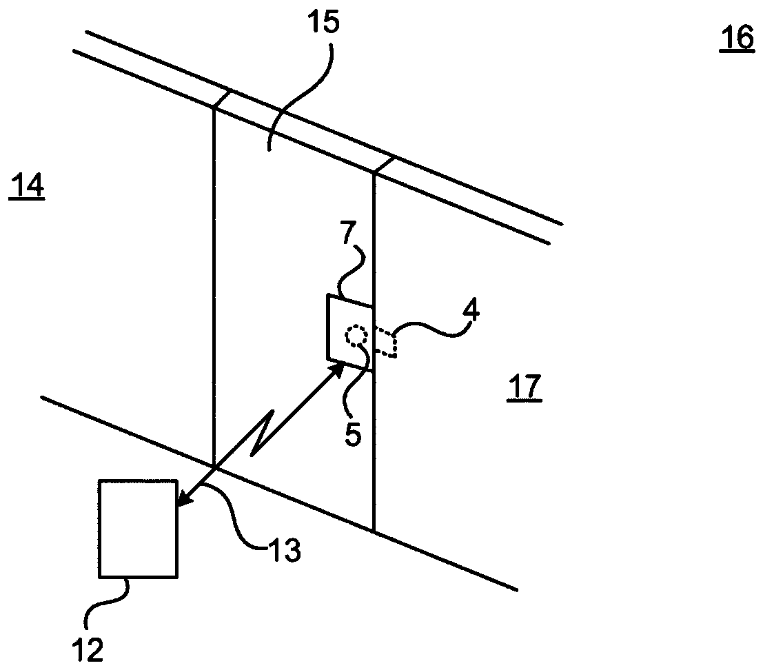
[0035] figure 1 It is a schematic diagram showing an environment in which the embodiments proposed herein can be applied. Access to the physical space 16 is restricted by a physical barrier 15 that can be selectively unlocked. The physical barrier 15 is located between the restricted physical space 16 and the accessible physical space 14. Note that the accessible physical...


PUM


Abstract

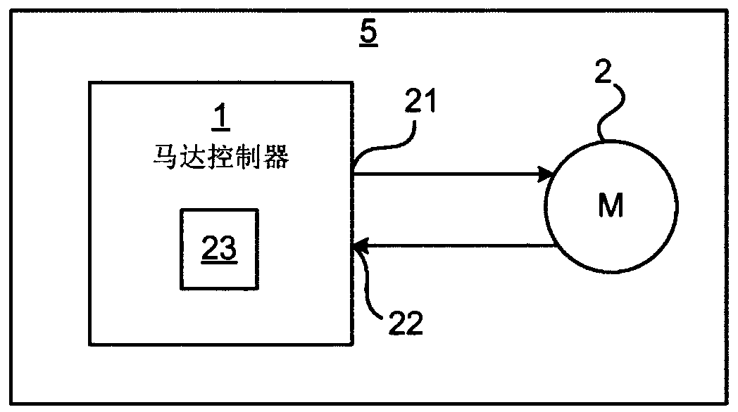
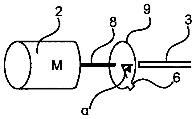
It is presented a motor controller configured to control movement of a motor to a mechanical end position. The motor controller comprises: a motor output configured to control an amount of energy being supplied to the motor; a motor input configured to measure a back electromotive force, EMF, voltage over the motor; and a control unit being configured to control the amount of energy being suppliedon the motor output based on back EMF measurements from the motor input when the motor output is in a state of not supplying energy to the motor wherein the control unit is configured to detect an end position of the motor based on changes of back EMF measurements.

Description

Technical field [0001] The invention relates to controlling motor movement. In particular, the present invention relates to controlling a motor based on changes in back EMF (electromotive force) measurement results. Background technique [0002] Electric motors are provided for a large number of different usage scenarios. One such scenario is the rotational movement of the motor to the mechanical end position. This scenario can be applied to an electronic lock, for example, where the control logic should be able to control the state of the lock as unlocked or locked. [0003] When controlling the motor to the mechanical end position, a DC (direct current) motor can be used. The DC motor may be powered by mains power, battery power, or other stored power (eg, power collected from electrical energy from mechanical movement). [0004] Traditional motor control for reaching the mechanical end position is to provide the motor with a pre-configured amount of electrical energy sufficien...

Claims


Application Information

Patent Timeline
Patent Type & Authority Applications(China)
IPC IPC(8): H02P6/182E05B47/00G07C9/00
CPCG07C9/00174H02P6/182E05B47/0001H02P6/17E05B47/0012E05B2047/0048H02P6/06
Inventor 托马斯·福斯贝里马切伊·尤尔恰克沃伊切赫·科茨瓦拉托马斯·皮沃瓦奇克
Owner ASSA ABLOY AB
Learn More