
A feeding device for bearing processing

A kind of bearing processing and bearing technology, which is applied in the field of bearing processing, can solve the problems of error-prone, poor flexibility, single application object of quantitative feeding device, etc., and achieve the effect of strong applicability, avoiding excessive material and less material

Active Publication Date: 2020-06-09
新昌县中实轴承有限公司
View PDF9 Cites 0 Cited by
  • Summary
  • Abstract
  • Description
  • Claims
  • Application Information

AI Technical Summary

Problems solved by technology

[0003] Problem 1: When assembling and loading rolling bearings, traditional manual loading is still used in most cases, which is inefficient and error-prone;
[0004] Problem 2: A small number of rolling bearings are equipped with feeding devices, and the feeding is generally uniform and continuous feeding, and the number of feeding materials needs to be manually counted and controlled, and the operation is cumbersome;
[0005] Question 3: For the quantitative feeding device, its feeding quantity cannot be adjusted, and the bearing needs different ball numbers according to different sizes, which leads to a single application object of the quantitative feeding device and poor flexibility in actual use
[0006] For the problems listed above, there is no better exploration and practice results under the existing technical conditions. Therefore, it is necessary to do further exploration and practice to solve the problems listed above

Method used


Image

  • A feeding device for bearing processing
  • A feeding device for bearing processing
  • A feeding device for bearing processing

Examples


Embodiment Construction

[0027] Embodiments of the present invention will be described below with reference to the drawings. In the process, in order to ensure the clarity and convenience of illustration, we may exaggerate the width of the lines or the size of the constituent elements in the diagram.

[0028] In addition, the following terms are defined based on the functions in the present invention, and may be different according to the user's or operator's intention or practice. Therefore, these terms are defined based on the entire content of this specification.

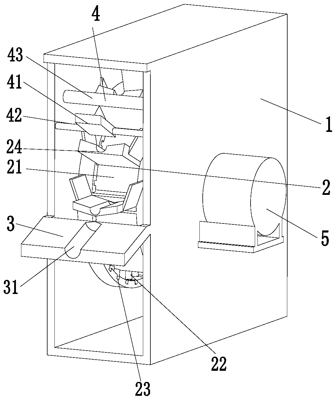
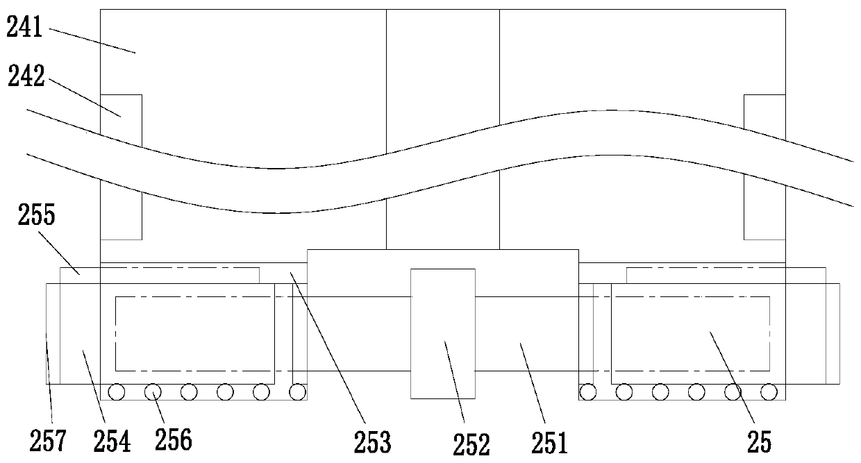
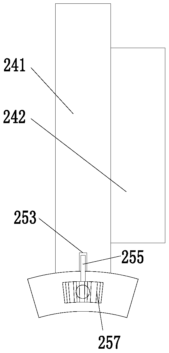
[0029] Such as Figure 1 to Figure 5 As shown, a feeding device for bearing processing includes a feeding box 1, a rotating assembly 2, a blanking plate 3 and a control mechanism 4, and the inside of the feeding box 1 is connected with a rotating assembly 2 through a bearing. A blanking plate 3 is installed in the middle of the front end of the loading box 1, and a control mechanism 4 is installed on the upper side of the front end of ...


PUM


Abstract

The invention relates to a feeding device for bearing machining. The feeding device comprises a feeding box, a rotating assembly, a discharging plate and a control mechanism, wherein the inner part ofthe feeding box is rotationally connected with the rotating assembly through a bearing, the discharging plate is arranged in the middle of the front end surface of the feeding box, and the upper sideof the front end of the feeding box is provided with a discharging mechanism; the rotating assembly comprises a rotating cylinder, the interior of the feeding box is rotationally connected with the rotating cylinder through the bearing, a groove is formed in the middle of the side wall of the rotating cylinder, clamping grooves are formed in the left side wall and the right side wall of the groove, and latchs are uniformly installed in the clamping grooves. According to the feeding device for bearing machining, the problems that manual feeding efficiency is low and mistakes are easily causedduring feeding of an existing rolling bearing assembly can be solved, a few mechanical feeding devices can continuously feeding, the feeding quantity is still required to be manually controlled, the operation is tedious and the feeding quantity of the quantitative feeding device is not adjustable, the flexibility is poor and the like are solved; the function of flexible and efficient feeding during assembly of the rolling bearing can be realized, the feeding device has the advantages of being high in feeding efficiency, adjustable in feeding quantity, and simple in feeding operation.

Description

technical field [0001] The invention relates to the field of bearing processing, in particular to a feeding device for bearing processing. Background technique [0002] There are many types of bearings according to different rolling elements. As far as rolling bearings are concerned, they generally consist of outer rings, inner rings, balls and cages. During the entire processing process of bearings, various parts that have been processed will need to be Assembly is called bearing assembly. During the assembly of rolling bearings, the balls need to be placed between the inner and outer rings, which will use the feeding device. However, under the existing conditions, there are still many problems in the assembly and feeding of rolling bearings: [0003] Problem 1: When assembling and loading rolling bearings, traditional manual loading is still used in most cases, which is inefficient and error-prone; [0004] Problem 2: A small number of rolling bearings are equipped with a...

Claims


Application Information

Patent Timeline
Patent Type & Authority Patents(China)
IPC IPC(8): B23P19/00
CPCB23P19/00B23P19/001
Inventor 张大方
Owner 新昌县中实轴承有限公司
Learn More