
Electric rotating lifting swing lifting rod

An electric rotating and boom technology, applied in the direction of load hanging components, entertainment, stage installations, etc., can solve the problems of waste of hanging points, poor stage effect, inability to realize multi-angle rotation, lift and swing of hanging points, etc., to achieve convenient configuration. Installation work, compact structure, uniform force effect

Pending Publication Date: 2019-08-06
江苏中惠舞台设备技术有限公司
View PDF1 Cites 1 Cited by
  • Summary
  • Abstract
  • Description
  • Claims
  • Application Information

AI Technical Summary

Problems solved by technology

[0004] The above-mentioned technical solution was also disclosed by the applicant in the first application, but after subsequent research by the applicant, it was found that only the multiple lifting points on the T-shaped beam assembly are lifted up and down, hoisted and rotated uniformly, the stage effect is not good, and it is impossible to realize multiple lifting points. Angle rotation lifts and swings, and the lifting point is wasted; it is necessary to improve the above technical solution

Method used


Image

  • Electric rotating lifting swing lifting rod
  • Electric rotating lifting swing lifting rod
  • Electric rotating lifting swing lifting rod

Examples


Embodiment Construction

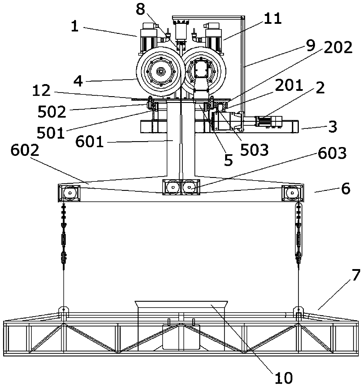
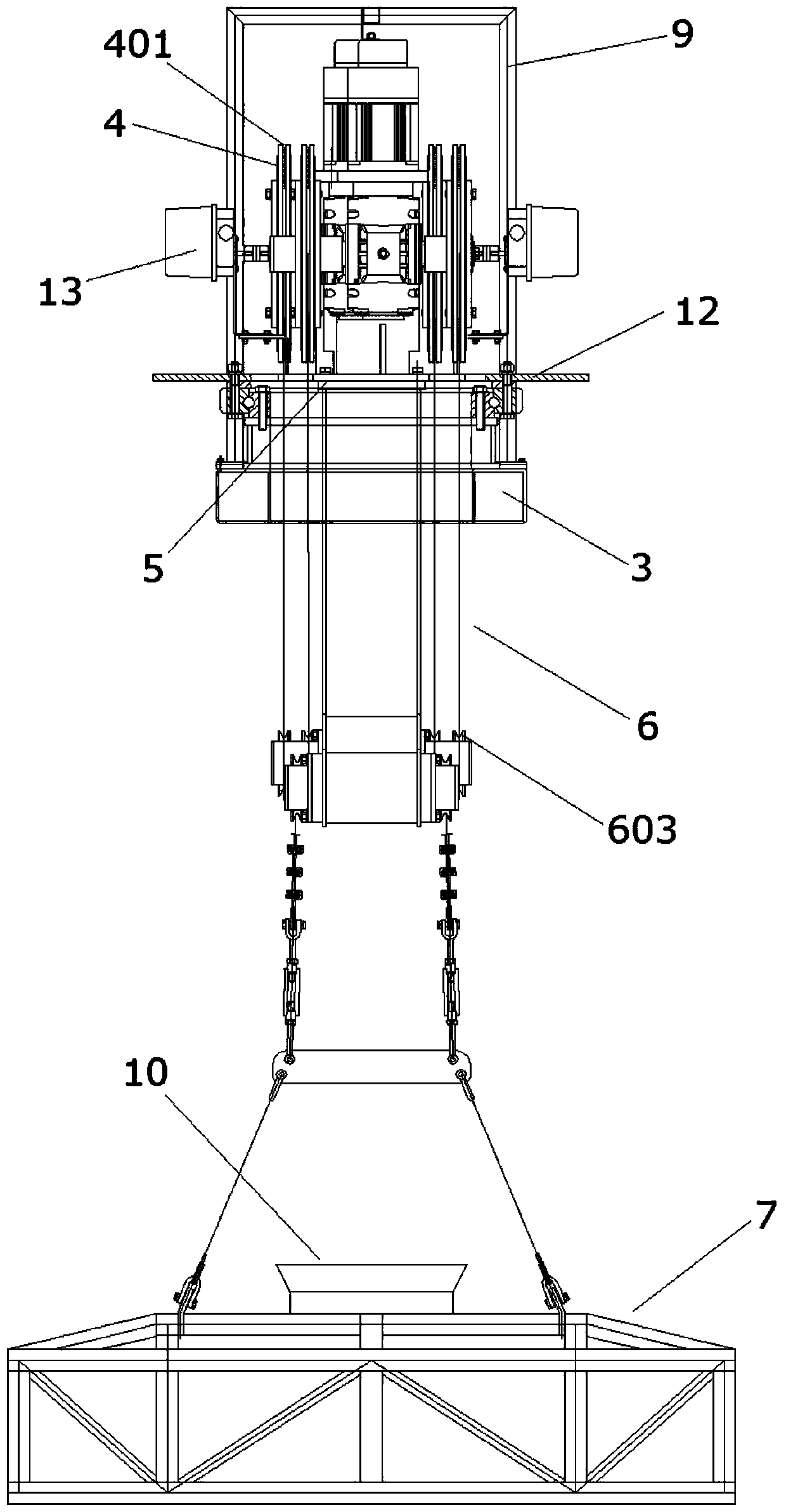
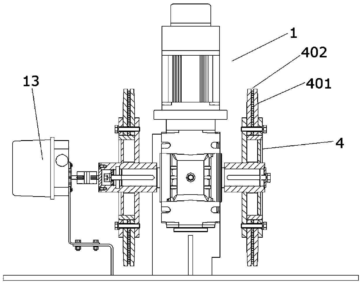
[0028] Such as figure 1 , 6 As shown, it is the electric rotary lifting and swinging boom of the present invention, which includes a rotating motor 2 and a base 3. The rotating motor 2 is connected to a slewing support 5, and a T-shaped beam assembly 6 is fixedly connected to the slewing support 5. The bottom of the T-beam assembly 6 is connected with a boom assembly 7, and the boom assembly 7 is provided with a plurality of suspension points for installing stage equipment; the base 3 is located below the slewing support 5, and includes at least Two lifting motors, that is, the first lifting motor 1 and the second lifting motor 11, each lifting motor is hoisted with different lifting points, and the at least two lifting motors are independent of each other; the rotating motor 2 is installed on the base 3 and placed horizontally.

[0029] The slewing support 5 of this embodiment has an inner ring 501 and an outer ring 502, and the slewing support 5 is fixed on the base 3 thro...


PUM


Abstract

The invention discloses an electric rotating lifting swing lifting rod. The electric rotating lifting swing lifting rod comprises a rotating motor and a base, the rotating motor is connected with a rotation support, a T beam assembly is fixedly connected to the rotation support, a lifting rod assembly is connected with the lower portion of the T beam assembly, multiple lifting points used for mounting of stage equipment are arranged on the lifting rod assembly, the base is located below the rotation support, at least two lifting motors are further included, each lifting motor lifts different lifting points, and the at least two lifting motors are independent of each other. According to the technical scheme, at least two motors are arranged for lifting of the lifting points, the two liftingmotors are independent, the lifting motors can be controlled, through setting, desynchrony lifting of the lifting points can be achieved, the rotating motors are used for rotating the lifting points,multi-angle swing rotation of the stage equipment (particularly, lamplight) can be achieved, and the stage effect is good.

Description

technical field [0001] The invention belongs to the technical field of stage equipment, in particular to an electric rotating, lifting and swinging suspender for safely suspending stage equipment. Background technique [0002] The horizontal boom can be used in studios, movie studios and theaters to hang lamps and lanterns. It mainly uses an electric transmission mechanism to drive the horizontal boom with lamps to rise, fall or move in parallel. The existing horizontal suspenders are poor in flexibility, all lamps on the same pole can only be on the same level, and the lighting distribution is limited; when the scenery is in place, because the light pole is too long, it cannot be lowered to the lowest point, and when the bulb is damaged Or if you can't get close to the lamps, you can only use other idle lamps instead, and there are many dead spots in the position distribution. Due to the defect of the transmission structure of the existing horizontal suspender, the horizon...

Claims


Application Information

Patent Timeline
IPC IPC(8): B66C1/14B66C13/08B66D1/12A63J1/02
CPCB66C1/14B66C13/08B66D1/12A63J1/02
Inventor 范博远王志克孙拂晓
Owner 江苏中惠舞台设备技术有限公司
Learn More