Bobbin case replacement device

A bobbin case and material storage technology, applied to auxiliary devices, embroidery machine mechanisms, embroidery machines, etc., can solve the problems of reducing embroidery machine output, increasing equipment manufacturing and maintenance costs, and manual recycling, so as to improve work efficiency and continuous Work stability, prolong continuous working time, and facilitate installation and disassembly

Inactive Publication Date: 2019-08-06
ZHUJI LIGHT IND TIMES ROBOT TECH CO LTD
View PDF0 Cites 4 Cited by
  • Summary
  • Abstract
  • Description
  • Claims
  • Application Information

AI Technical Summary

Problems solved by technology

[0002] At present, the bottom thread of the computer embroidery machine in use is composed of a bobbin case and a bobbin. When the embroidery machine runs out of bottom thread, the bobbin case (bobbin) needs to be replaced. Now all of them are replaced manually. , the embroidery machine should be completed in the shutdown state
There are the following problems: the embroidery machine needs to stop for 12-20 minutes every day for a single machine head to replace the bobbin case (bobbin). Reduce embroidery machine output
But this type of equipment in the prior art only utilizes the mechanical execution part to complete bobbin case dismounting and the operation according to
[0004] Problem 1: The disassembled empty bobbin case is placed in the receiving hopper of the device and needs to be recovered manually
And the bobbin case used for replacement on the device also needs to be supplemented and maintained in time. Since the shuttle body, machine head and related configuration components on each station of the embroidery machine are closely arranged, the operator leans over to recover and

Method used


Image

  • Bobbin case replacement device
  • Bobbin case replacement device
  • Bobbin case replacement device

Examples


Embodiment 1

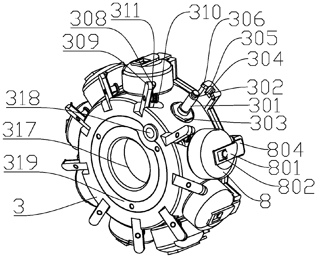
[0041] Such as figure 1 As shown, the embodiment of the present invention provides a bobbin case 8 replacement device, which includes a bobbin case 8 grasping part 4 and a bobbin case storage part, the bobbin case storage part is arranged under the bobbin case 8 grasping part 4, and the shuttle The shell storage part is provided with one or more bobbin case storage devices; the bobbin case storage device includes a storage turntable 3, and a number of bobbin case 8 storage stations are arranged around the storage turntable 3, and the bobbin case 8 storage stations Including a mandrel 301 for placing the bobbin case 8; the mandrel 301 is fixedly connected to the side of the storage carousel 3 along the radial direction of the storage carousel 3; the two sides of the mandrel 301 are respectively equipped with bobbin case 8 positioning pieces 304 and thread clamping structure.

[0042] The top of the mandrel 301 is provided with an annular positioning groove 302 for positioning ...

Embodiment 2

[0053] Such as image 3 , Figure 4 , Figure 5 As shown, the embodiment of the present invention has made the following improvements on the basis of embodiment 1:

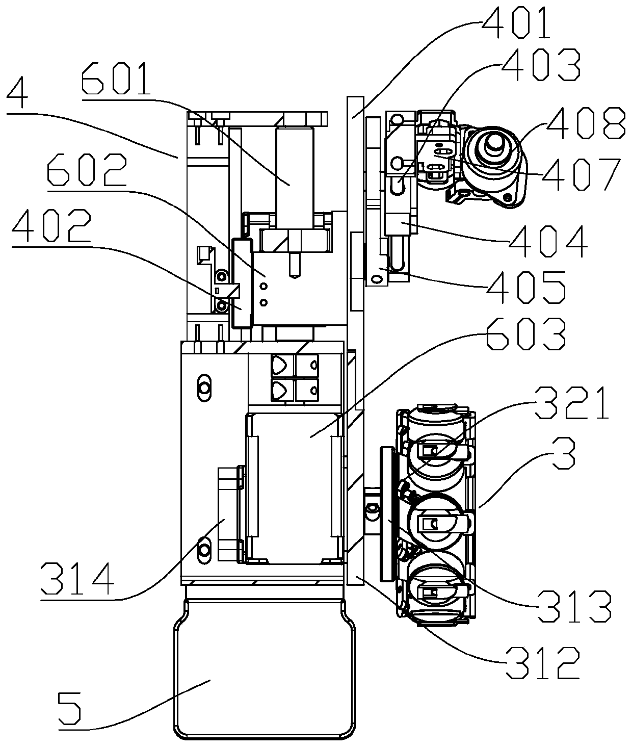
[0054] The bobbin case storage part also includes a first base plate 312 and a first servo motor 314, the first servo motor 314 is arranged on one side of the first base plate 312, and the output shaft of the first servo motor 314 passes through the first base plate 312 Connect the driving disc 313 of the bobbin case storage device.

[0055] The grasping part 4 of the bobbin case 8 includes a second base plate 401, a swing telescopic mechanism and a mechanical finger mechanism. The swing telescopic mechanism is rotatably connected to the second substrate 401. , the mechanical finger mechanism points to the bobbin case 8 storage station on the storage carousel 3, and the first base plate 312 and the second base plate 401 are fixedly connected.

[0056] The swing telescopic mechanism includes a second servo moto...

Embodiment 3

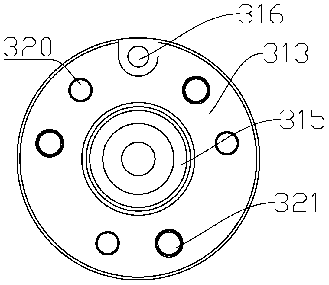
[0063] combine Figure 9 As shown, the embodiment of the present invention has made the following improvements on the basis of Embodiment 2: the bobbin case storage part is provided with a plurality of bobbin case storage devices, and each bobbin case storage device is coaxially fixedly connected to the first On the output shaft of the servo motor 314; offset or keep the same distance between two adjacent bobbin housing storage devices, and the positioning pins 316 on each drive disc 313 are located on the same straight line.

[0064] Further, when the storage stations of the bobbin case 8 are equiangularly arranged on the outside of the storage carousel 3, the central angles corresponding to the two adjacent mandrels 301 are a, and the positions of any two bobbin case storage devices are The central angle formed by the positioning pin 316 on a plane parallel to the driving disk 313 and the axis of the driving shaft 315 is an integer multiple of a.

[0065] The bobbin case re...


PUM


Abstract

The invention provides a bobbin case replacement device. A plurality of bobbin case storage stations can be arranged and used for storing dismantled bobbin cases and standby bobbin cases, the continuous work time of the bobbin case replacement device can be prolonged, when the standby bobbin cases on bobbin case storage devices are used up, an operator can directly replace the bobbin case storagedevices to supplement the standby bobbin cases, and the work efficiency is greatly improved. Each bobbin case storage device comprises a storage rotary disc and several bobbin case storage stations surrounding the storage rotary disc, and the bobbin case storage stations comprise mandrels used for placement of the bobbin cases; the mandrels are fixedly connected to the side surfaces of the storagerotary discs in the axial directions of the storage rotary discs; a bobbin case locating piece and a thread head clamping structure are respectively installed on the two sides of each mandrel. The invention further provides the bobbin case replacement device, a bobbin case replacement system and a bobbin case replacement method based on the bobbin case storage device.

Description

technical field [0001] The invention relates to the field of textile equipment, in particular to the technical field of automatic bobbin thread changing and bobbin case changing for embroidery machines. Background technique [0002] At present, the bottom thread of the computer embroidery machine in use is composed of a bobbin case and a bobbin. When the embroidery machine runs out of bottom thread, the bobbin case (bobbin) needs to be replaced. Now all of them are replaced manually. , the embroidery machine should be completed in a stopped state. There are the following problems: the embroidery machine needs to stop for 12-20 minutes every day for a single machine head to replace the bobbin case (bobbin). Reduce embroidery machine output. [0003] Existing multi-head embroidery machine is that a row of head stations is set on its frame, a shuttle case is set at each head station, and a head for installing the bobbin case is set in the shuttle case. The bobbin case is pro...

Claims


Application Information

Patent Timeline
IPC IPC(8): D05C13/06
CPCD05C13/06
Inventor 徐海苗
Owner ZHUJI LIGHT IND TIMES ROBOT TECH CO LTD
Why Eureka
Try Eureka