Al technical title is built by PatSnap Al team. It summarizes the technical point description of the patent document.
A calcining furnace and carbon technology, which is applied in the field of carbon calcining furnace equipment, can solve the problems of large workload, low work efficiency, inconvenient shock absorption and protection, etc., and achieve the effect of high work efficiency and simple operation.
Inactive Publication Date: 2020-06-26
JINAN HUAYANG CARBON
View PDF4 Cites 0 Cited by
Summary
Abstract
Description
Claims
Application Information
AI Technical Summary
This helps you quickly interpret patents by identifying the three key elements:
Problems solved by technology
Method used
Benefits of technology
Problems solved by technology
[0002] When the existing carbon calciner discharges the product, it usually performs manual discharge, which has a large workload and low work efficiency, and the existing carbon calciner is not convenient for shock absorption and protection of the product, and the pushing effect is poor , inconvenient to organize
Method used
Image
Click on the blue label to locate the original text in one second.
Reading with bidirectional positioning of images and text.
Examples
Embodiment Construction
[0024] In order to make the technical means, creative features, goals and effects achieved by the present invention easy to understand, the present invention will be further described below in conjunction with specific embodiments.
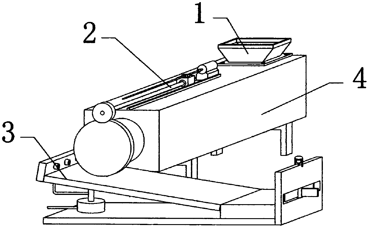
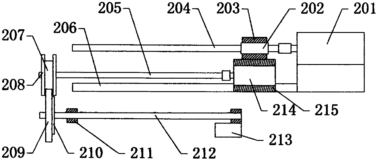
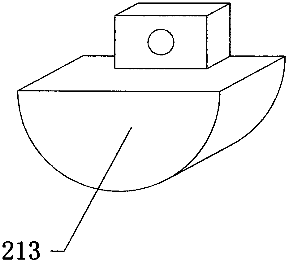
[0025] see Figure 1-Figure 9 , the present invention provides a technical solution: the discharge device of the carbon calciner includes a calciner main body 4, and the rear part of the upper end surface of the calciner main body 4 is fixed with a feeding hopper 1, and the feeding hopper 1 is located at the rear side of the discharging mechanism 2. The material mechanism 2 is fixed on the upper end of the main body 4 of the calciner, and a push mechanism 3 is arranged at the front and bottom of the main body 4 of the calciner. , screw mandrel 204, rotating rod 205, baffle plate 206, circular gear one 207, limiting plate 208, circular gear two 209, sealing plate 210, ring 211, connecting rod 212, push block 213, motor two 214 and Slider 215, push...
PUM
Abstract
The invention provides a discharge device of a carbon calciner. The discharge device includes a calciner main body. A feeding hopper is fixed to the rear part of the upper end face of the calciner main body. The feeding hopper is located at the rear side of a discharge mechanism. The discharge mechanism is fixed to the upper end of the calciner main body. A push mechanism is arranged at the frontlower part of the calciner main body. The discharge mechanism includes a motor I, a nut seat, a fixing block, a screw rod, a rotating rod, a baffle plate, a circular gear I, limit plates, a circular gear II, a sealing plate, a circular ring, a connecting rod, a push block, a motor II and a sliding block. The push mechanism includes a hollow plate, nozzles, a connecting hose, a bottom plate, a sealing cylinder, a supporting platform, a vertical plate, a poking plate, a motor III, a push inclined plate, a telescopic rod, a fixed ring, a piston plate, a pulley and a guide rail. Compared with theprior art, the discharge device of the carbon calciner has the beneficial effects that the discharge device realizes the purpose of automatic discharge and automatic reset, has high work efficiency, realizes the purpose of shock absorption and protection, avoids collision damage, and facilitates rapid push.
Description
technical field [0001] The invention relates to a discharge device for a carbon calciner, belonging to the field of carbon calciner equipment. Background technique [0002] When the existing carbon calciner discharges the product, it usually performs manual discharge, which has a large workload and low work efficiency, and the existing carbon calciner is not convenient for shock absorption and protection of the product, and the pushing effect is poor , It is inconvenient to organize. Contents of the invention [0003] Aiming at the deficiencies in the prior art, the purpose of the present invention is to provide a discharge device for a carbon calciner to solve the problems raised in the above-mentioned background technology. [0004] In order to achieve the above object, the present invention is achieved through the following technical solutions: the discharge device of the carbon calciner includes a calciner main body, a feeding hopper is fixed at the rear of the upper ...
Claims
Application Information
Patent Timeline
Application Date:The date an application was filed.
Publication Date:The date a patent or application was officially published.
First Publication Date:The earliest publication date of a patent with the same application number.
Issue Date:Publication date of the patent grant document.
PCT Entry Date:The Entry date of PCT National Phase.
Estimated Expiry Date:The statutory expiry date of a patent right according to the Patent Law, and it is the longest term of protection that the patent right can achieve without the termination of the patent right due to other reasons(Term extension factor has been taken into account ).
Invalid Date:Actual expiry date is based on effective date or publication date of legal transaction data of invalid patent.