Optical fiber sorting device and optical fiber assembly line

An assembly line and finishing device technology, applied in the direction of light guides, optics, optical components, etc., can solve problems that are difficult to realize, and achieve the effect of avoiding damage and improving assembly efficiency

Active Publication Date: 2019-02-22
CHENGDU UNIV OF INFORMATION TECH +1
View PDF23 Cites 2 Cited by
  • Summary
  • Abstract
  • Description
  • Claims
  • Application Information

AI Technical Summary

Problems solved by technology

[0004] Aiming at the above-mentioned deficiencies in the prior art, the present invention provides an optical fiber finishing device and an optical fiber assembly line, which solves the problem that it is difficult to set the plastic sleeve on the optical fiber through automatic assembly equipment

Method used


Image

  • Optical fiber sorting device and optical fiber assembly line
  • Optical fiber sorting device and optical fiber assembly line
  • Optical fiber sorting device and optical fiber assembly line

Examples


Embodiment Construction

[0023] In order to make the purpose, technical solutions and advantages of the present invention clearer, the technical solutions in the present invention are clearly and completely described below. Apparently, the described embodiments are part of the embodiments of the present invention, not all of them. Based on the embodiments of the present invention, all other embodiments obtained by persons of ordinary skill in the art without creative efforts fall within the protection scope of the present invention.

[0024] The present invention will be further described below in conjunction with accompanying drawing:

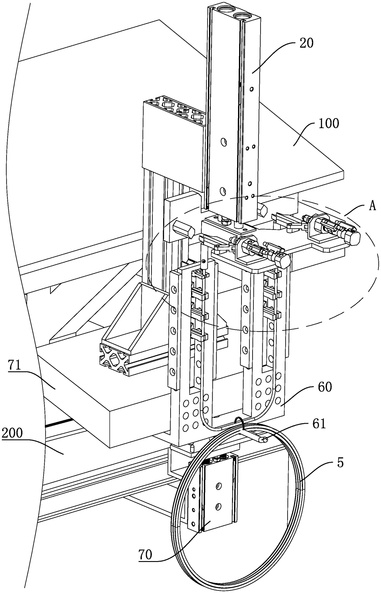
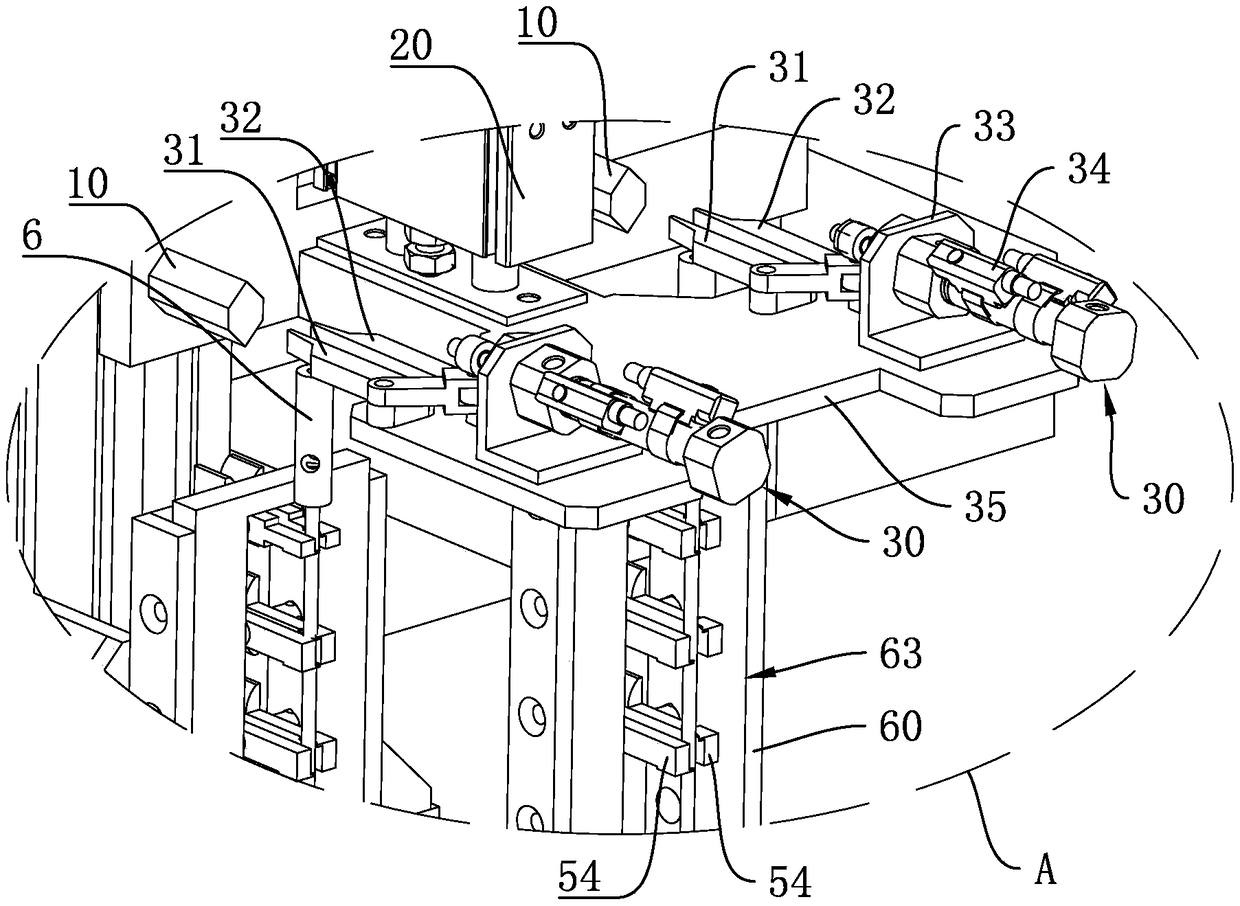
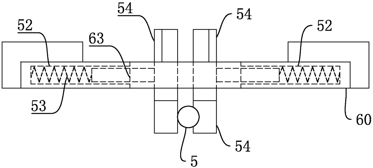
[0025] Such as Figure 1-Figure 3 As shown, the present invention provides an optical fiber finishing device, which includes a tooling plate 60 and two grasping mechanisms 30. The tooling plate 60 is provided with a plurality of clamping blocks 54, and each clamping block 54 is connected to the tooling plate 60 through a spring 53. Two clamping blocks 54 form a pair ...


PUM


Abstract

The invention discloses an optical fiber sorting device and an optical fiber assembly line. The device comprises a tooling plate and two grasping mechanisms. The tooling plate is provided with a plurality of clamping blocks, each of the clamping blocks is connected to the tooling plate by a spring, two adjacent clamping blocks in the same plane in the multiple clamping blocks form a pair, the clamping blocks are arranged in two rows on the tooling plate, each pair of the clamping blocks is used for abutting each other to clamp an end of an optical fiber, two ends of the optical fiber face up and are sleeved with plastic sleeves, and two ends of the optical fiber just face the two grasping mechanisms. The grasping mechanisms are used for clamping or loosening the plastic sleeves, and the grasping mechanisms are connected to a vertical driving mechanism which is used for driving the grasping mechanisms to move up and down such that the plastic sleeves clamped by the two grasping mechanisms pass through two ends of the optical fiber. The optical fiber sorting device also comprises two pushing blocks, and each of the pushing blocks is used for moving up and down to abut against a pairof two clamping blocks in clamping blocks of one row to open the two clamping blocks.

Description

technical field [0001] The invention belongs to the technical field of optical fiber processing equipment, and in particular relates to an optical fiber finishing device and an optical fiber assembly line. Background technique [0002] The fiber optic head is a commonly used part on the fiber, especially the LC fiber head is widely used. By inserting the fiber head into the end of the fiber, several fibers can be permanently or detachably connected together. The fiber head is also It has the function of protecting the optical fiber. Its structure includes at least a rubber sleeve and a fiber core head. During the assembly process, it is necessary to put a plastic sleeve on the fiber first. The plastic sleeve can slide on the fiber, and then the fiber core head and other joints The accessories are connected to the end of the optical fiber, and finally the plastic sleeve is slid to the connection between the fiber core head and the rubber sleeve for thermal connection. [000...

Claims


Application Information

Patent Timeline
Patent Type & Authority Applications(China)
IPC IPC(8): G02B6/36G02B6/38
CPCG02B6/36G02B6/3628G02B6/38Y02P40/57
Inventor 刘鹏张庆军陈丹羊银刘凯明涛白竹川
Owner CHENGDU UNIV OF INFORMATION TECH
Why Eureka
Try Eureka