
Threaded blind hole detection device

A detection device, threaded blind hole technology, applied in the direction of measuring devices, mechanical measuring devices, mechanical devices, etc., can solve the problems of inability to guarantee the machining accuracy of workpieces, large equipment assembly errors, low assembly efficiency, etc., and achieve fast detection speed, Reduce the number of clamping and facilitate the effect of starting and stopping

Inactive Publication Date: 2019-08-06
烟台双赫机电制造有限公司 +1
View PDF6 Cites 0 Cited by
  • Summary
  • Abstract
  • Description
  • Claims
  • Application Information

AI Technical Summary

Problems solved by technology

[0002] Drilling is a way of processing workpieces to facilitate the assembly of workpieces such as connection and guidance. Sometimes it is necessary to tap the inner wall of the hole to form threaded holes to meet the needs. In order to facilitate the installation of workpieces, sometimes it is necessary to drill more than one workpiece on a workpiece. Since the assembly relationship needs to be satisfied, the relative position of each hole is required to be accurate, so as to avoid assembly errors and make it difficult to assemble the workpiece. However, there is no special equipment for detecting the holes on the workpiece in the existing equipment. As a result, the machining accuracy of the workpiece cannot be guaranteed, which further leads to large equipment assembly errors and low assembly efficiency

Method used


Image

  • Threaded blind hole detection device
  • Threaded blind hole detection device
  • Threaded blind hole detection device

Examples


Embodiment Construction

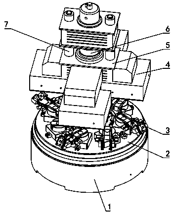
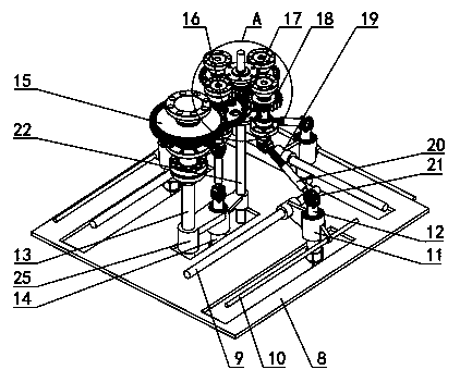
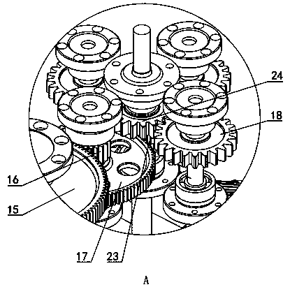
[0032] Figure 1~8 It is the best embodiment of the present invention, below in conjunction with attached Figure 1~8 The present invention will be further described.

[0033]A threaded blind hole detection device, including a lifting mechanism, a mounting frame 8, a fixture 3 and a rotating mechanism, the fixture 3 is arranged on the lower side of the mounting frame 8, multiple fixtures 3 are arranged around the rotating mechanism, and the mounting frame 8 is arranged at intervals around the lifting mechanism There are multiple, and each mounting frame 8 is provided with a plurality of translation mechanisms, and each translation mechanism is slidably connected with a drill rod, and a buffer spring is arranged between the drill rod and the translation mechanism, and the lower end of the drill rod is connected with a tap through a power device; 3 comprises turntable 33, swing arm and vise 37, and turntable 33 rotations are installed on the rotating mechanism, and turntable is...


PUM


Abstract

The invention relates to a threaded blind hole detection device and belongs to the technical field of threaded hole detection equipment. The device is characterized in that a plurality of clamps (3) are arranged around a rotating mechanism; a plurality of mounting frames (8) are arranged around a lifting mechanism at intervals; each mounting frame (8) is provided with a plurality of translationalmovement mechanisms; each translational movement mechanism is connected with a drill rod in a sliding mode; a buffer spring is arranged between the drill rod and the corresponding translational movement mechanism; the lower end of each drill rod is connected with a screw tap through a power device; a turntable is connected with a clamp motor for driving the turntable to rotate; two swing arms aresymmetrically arranged to two sides of the turntable (33); a jaw vice (37) is installed between the two swing arms; a first swing arm motor is arranged on the turntable (33); and the output shaft of the first swing arm motor is connected with the two swing arms. According to the threaded blind hole detection device, both the relative position and threaded screw of a threaded through hole can be detected; and the detection of the threaded holes of a plurality of surfaces can be completed with one-time clamping, and therefore, the number of the times of clamping can be reduced.

Description

technical field [0001] A threaded blind hole detection device belongs to the technical field of threaded hole detection equipment. Background technique [0002] Drilling is a way of processing workpieces to facilitate the assembly of workpieces such as connection and guidance. Sometimes it is necessary to tap the inner wall of the hole to form threaded holes to meet the needs. In order to facilitate the installation of workpieces, sometimes it is necessary to drill more than one workpiece on a workpiece. Since the assembly relationship needs to be satisfied, the relative position of each hole is required to be accurate, so as to avoid assembly errors and make it difficult to assemble the workpiece. However, there is no special equipment for detecting the holes on the workpiece in the existing equipment. As a result, the processing accuracy of the workpiece cannot be guaranteed, which further leads to large errors in equipment assembly and low assembly efficiency. Contents ...

Claims


Application Information

Patent Timeline
IPC IPC(8): G01B5/00H02P25/18
CPCG01B5/00H02P25/18
Inventor 孙贤明付全武马立修覃文峰李家鹏
Owner 烟台双赫机电制造有限公司
Learn More