Electroplating support plate for ultrathin circuit board, electroplating system and electroplating method

A circuit board and support board technology, which is applied in the direction of printed circuit, printed circuit manufacturing, electrical components, etc., can solve the problem of bending and breaking at the pinch point between the circuit board and the fixture, the weight of the ultra-thin circuit board cannot be dropped vertically, the tank body, the anode Avoid problems such as baffle contact and collision, so as to avoid uneven thickness of the electroplating layer, ensure the quality of electroplating, and reduce the scrap rate

Pending Publication Date: 2021-04-06
TIANJIN PRINTRONICS CIRCUIT CORP
View PDF8 Cites 0 Cited by
  • Summary
  • Abstract
  • Description
  • Claims
  • Application Information

AI Technical Summary

Problems solved by technology

[0003] First, the ultra-thin circuit board cannot be dropped vertically into the electroplating tank due to its light weight, and it is easy to contact and collide with the tank body and the anode baffle;
[0004] Second, due to its large size and low weight, the ultra-thin circuit board is easy to be bent and twisted in the electroplating tank, resulting in dif

Method used


Image

  • Electroplating support plate for ultrathin circuit board, electroplating system and electroplating method
  • Electroplating support plate for ultrathin circuit board, electroplating system and electroplating method
  • Electroplating support plate for ultrathin circuit board, electroplating system and electroplating method

Examples


Example Embodiment

[0040]Next, the technical solutions in the embodiments of the present invention will be apparent from the embodiment of the present invention, and it is clearly described, and it is understood that the described embodiments are merely embodiments of the present invention, not all of the embodiments. Based on the embodiments of the present invention, there are all other embodiments obtained without making creative labor without making creative labor premises.

[0041]It should be noted that the component is referred to as "fixed to" another component, which can be directly in another component or may also exist. When a component is considered to be "connected" another component, it can be directly connected to another component or may exist at the same time. When a component is considered "set to" another component, it can be directly set on another component or may exist at the same time. The terms "vertical", "horizontal", "left", "right", and similar expressions are merely for illust...


PUM


Abstract

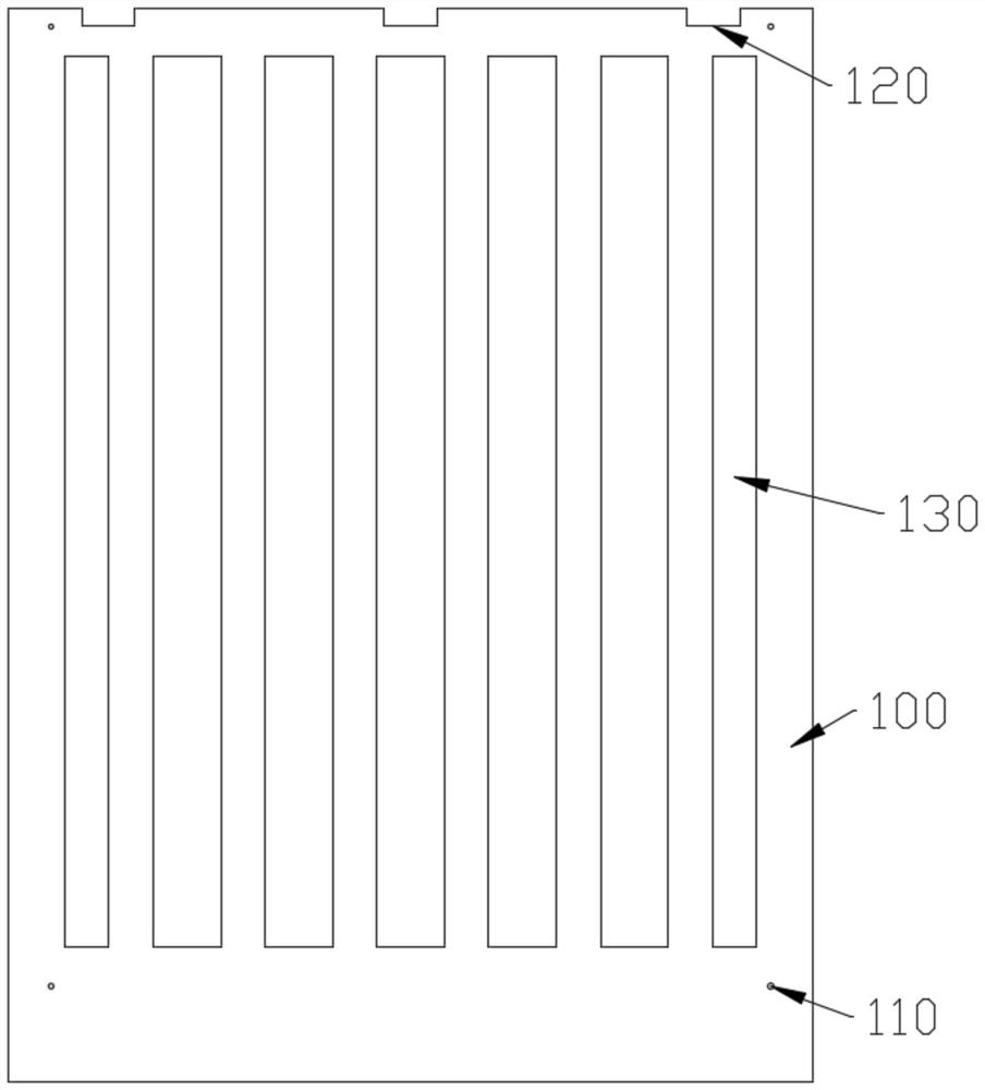
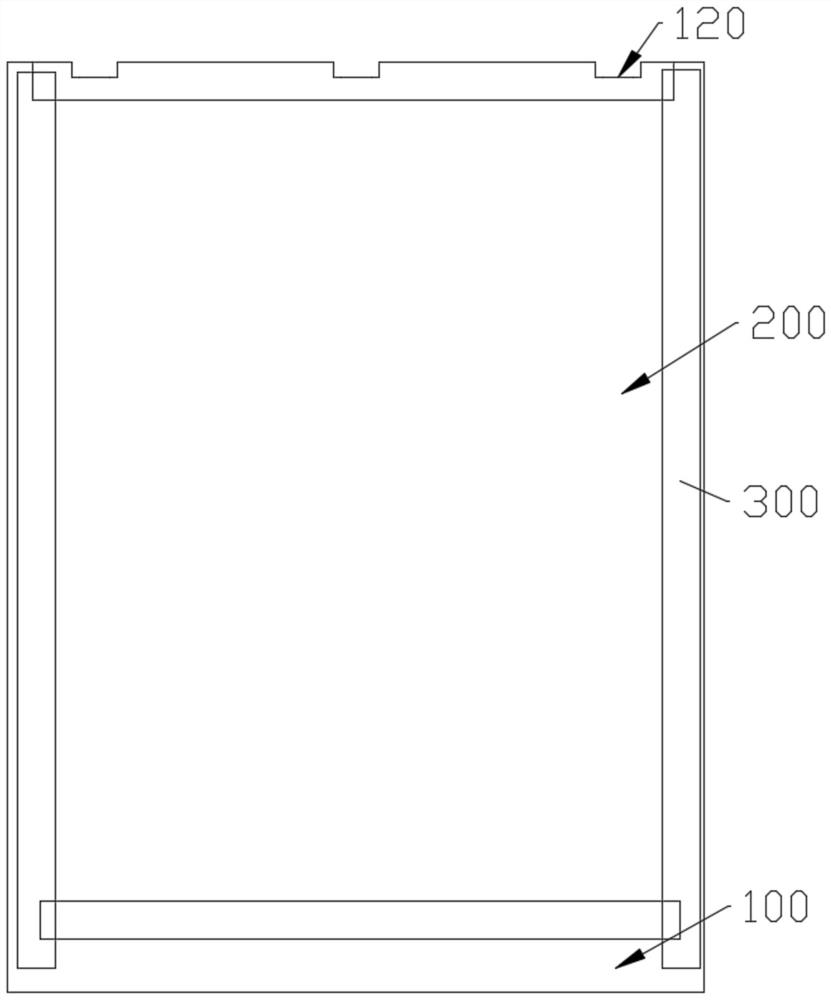
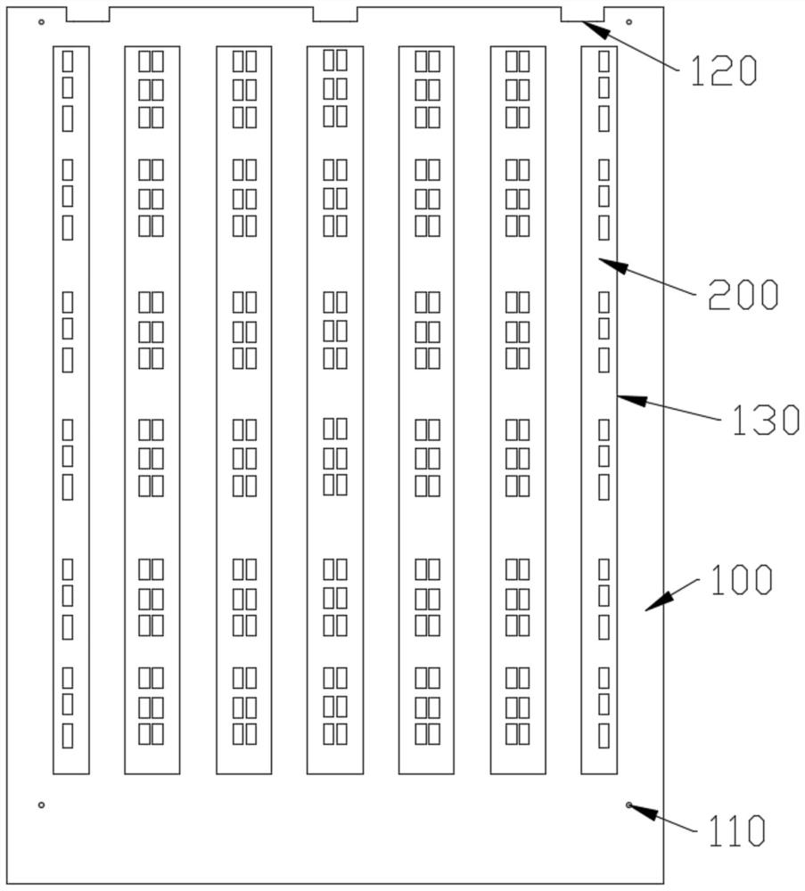
The invention provides an electroplating support plate for an ultrathin circuit board. The electroplating support plate comprises a plurality of positioning holes arranged on the electroplating support plate, the positions of the positioning holes are matched with the position of the ultrathin circuit board so as to realize the positioning of the ultrathin circuit board, the electroplating support plate is fixedly connected with the ultrathin circuit board through an adhesive tape, and a plurality of electroplating positioning grooves and windows are formed in the upper side of the electroplating supporting plate. By arranging the positioning holes and the electroplating positioning grooves and the windows, the relative position of the ultrathin circuit board is more accurate in the electroplating process, operation is easy, the quality problem that the thickness of an electroplated layer is uneven due to the fact that the electroplating position is shielded is solved, and the electroplating quality of products is guaranteed; and the electroplating support plate and the ultrathin circuit board are fixed through the adhesive tape, so that the ultrathin circuit board can ascend and descend along with the weight of the electroplating support plate in the electroplating process, the problem that the ultrathin circuit board is bent and even broken due to the fact that the weight of the ultrathin circuit board is too small is solved, and the rejection rate of the products is reduced.

Description

Technical field[0001]The present invention relates to the technical field of circuit board processing apparatus, and more particularly to an electroplating support plate for ultra-thin circuit board, a plating system, and a plating method thereof.Background technique[0002]At present, with the demand for miniaturization of electrical appliances, more and more mobile electronic devices have put forward light and thin requirements; therefore, the ultra-thin circuit board has been widely used; however, during the production of a light board, There is a problem:[0003]First, the ultra-thin circuit board cannot be vertically down to the electroplating tank due to the weight of the weight, and contact collisions in the electroplating groove, the anode baffle, etc.[0004]Second, the ultra-thin circuit board is large and the weight is too small, which is easy to be in a curved and distorted state in the plating tank, resulting in a different distance from the anode, thereby affecting product q...

Claims


Application Information

Patent Timeline
IPC IPC(8): C25D17/08C25D7/00H05K3/18
CPCC25D17/08C25D7/00H05K3/188
Inventor 王刚耿波
Owner TIANJIN PRINTRONICS CIRCUIT CORP
Why Eureka
Try Eureka