
Redundant device, master-slave module determination method, topology system and communication decision method

A technology of redundant modules and redundant equipment, applied in the field of system redundancy, can solve the problems of CPU resource occupation, complex system structure programming, and difficult maintenance, and achieve the effects of simplifying circuits, reducing costs, and improving efficiency

Active Publication Date: 2019-08-06
重庆川仪控制系统有限公司
View PDF9 Cites 5 Cited by
  • Summary
  • Abstract
  • Description
  • Claims
  • Application Information

AI Technical Summary

Problems solved by technology

[0004] In view of the above-mentioned shortcomings of the prior art, the purpose of the present invention is to provide a redundant device, a master-slave module judgment method, a topology system and a communication decision-making method, which are used to solve the complexities of the prior art redundant module system structure and software programming. , It is difficult to repair after a fault and takes up a lot of CPU resources

Method used


Image

  • Redundant device, master-slave module determination method, topology system and communication decision method
  • Redundant device, master-slave module determination method, topology system and communication decision method
  • Redundant device, master-slave module determination method, topology system and communication decision method

Examples


Embodiment 1

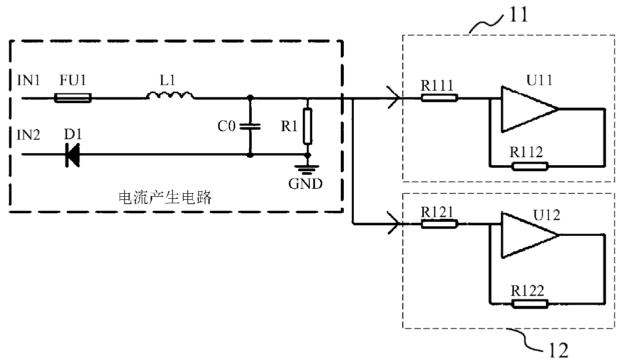
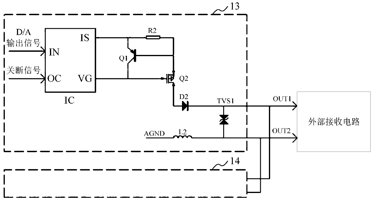
[0036] This embodiment provides a redundant device, please refer to figure 1 and figure 2 , which are respectively shown as the circuit diagram of the input redundant device of the present invention and the circuit diagram of the output redundant device of the present invention. The redundant equipment includes:

[0037] a first redundancy module;

[0038] The second redundancy module, as a backup slave redundancy module, is used to replace the first redundancy module when the first redundancy module fails to work as the master redundancy module;

[0039] Both the first redundancy module and the second redundancy module are provided with a master communication port and a slave communication port.

[0040] see figure 1 , the redundant device is an input redundant device, and the input redundant device includes an input first redundancy module and an input second redundancy module, figure 1 It is specifically represented as an input master redundancy module 11 and an input...

Embodiment 2

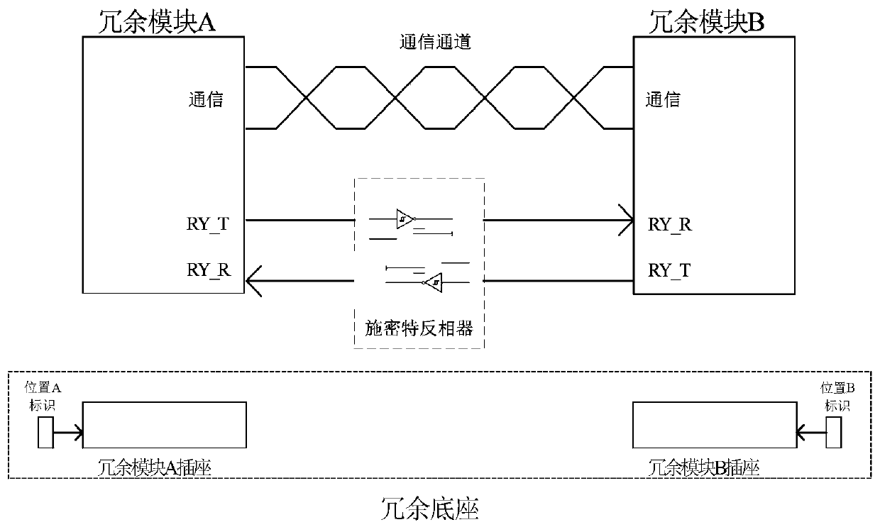
[0049] This embodiment provides a master-slave module determination method, which is applied to redundant equipment, and the redundant equipment includes at least two redundant modules; please refer to image 3 and Figure 4 , respectively showing a schematic diagram of the circuit connection of the master-slave module and a schematic flowchart of a method for determining the master-slave module in an embodiment. like image 3 As shown, there are pins (signal sending pin RY_T and signal receiving pin RY_R) used to transmit master-slave determination signals on redundant modules A and B, where the signal sending pin (RY_T) is used to send signals to other redundant The module sends a master-slave judgment signal, and the signal receiving pin (RY_R) is used to receive the master-slave judgment signal from other redundant modules. In this embodiment, the master-slave judgment signal includes a high level signal for Communication transmission of the master-slave judgment informa...

Embodiment 3

[0068] This embodiment provides a topology system, please refer to Figure 5 , is shown as a structural principle diagram of the redundant topology system of the present invention in an embodiment, and the topology system 2 includes:

[0069] A controller; and at least one redundant device, connected to the controller; wherein, the redundant device includes: a first redundant module, connected to the controller through the main communication port of the first redundant module or The slave communication port of the first redundancy module is connected in communication; the second redundancy module is connected to the controller through the master communication port of the second redundancy module or the slave communication port of the second redundancy module; wherein, The controller is used to execute the communication port switching strategy to replace the main communication port with the slave communication port when acquiring communication fault information and performing a...


PUM


Abstract

The invention provides a redundant device, a master-slave module determination method, a topology system and a communication decision method. The redundant device comprises a first redundant module and a second redundant module. The second redundant module is used as a standby slave redundant module and is used for replacing the first redundant module when the first redundant module is used as a master redundant module to work and has a fault. The first redundant module and the second redundant module are provided with main communication ports and slave communication ports. The topology systemcomprises a controller, the first redundant module and the second redundant module, wherein the first redundant module is communicated and connected to the controller through the main communication port of the first redundant module or the slave communication port of the first redundant module; and the second redundant module is communicated and connected to the controller through the main communication port of the second redundant module or the slave communication port of the second redundant module. By using the redundant device, the master-slave module determination method, the topology system and the communication decision method, cost is reduced through simplifying a circuit, and simultaneously, programming difficulty is reduced and CPU efficiency and system reliability are increased.

Description

technical field [0001] The invention belongs to the technical field of system redundancy, and relates to a redundant module and method, in particular to a redundant device, a master-slave module judgment method, a topology system and a communication decision method. Background technique [0002] Distributed systems often involve the design of redundant modules. The module redundancy of existing schemes usually sends uninterrupted pulses to the other party to indicate its existence. The confirmation of the master-slave module is generally through preemption. The existing technology adopts many devices and is relatively complicated, and maintenance after failure requires a variety of instruments, which is very inconvenient; at the same time, software programming is also relatively complicated and takes up more CPU resources. [0003] Therefore, how to provide a redundant device, a master-slave module judgment method, a topology system, and a communication decision-making metho...

Claims


Application Information

Patent Timeline
Patent Type & Authority Applications(China)
IPC IPC(8): G05B9/03
CPCG05B9/03Y02P90/02
Inventor 潘云川
Owner 重庆川仪控制系统有限公司
Learn More