
Photoelectric signal peak value detection method and device for flow cytometer, and flow cytometer

A flow cytometer and photoelectric signal technology, applied in the field of cell biology, can solve the problems of difficult real-time judgment of signal peaks, large amount of calculation, repeated detection of window junctions, etc., and achieves low programming difficulty, stable operation, and fast calculation speed. Effect

Inactive Publication Date: 2013-09-18
青岛爱德生物科技发展基金企业(普通合伙)
View PDF4 Cites 5 Cited by
  • Summary
  • Abstract
  • Description
  • Claims
  • Application Information

AI Technical Summary

Problems solved by technology

This method has a large amount of calculation, and it is difficult to realize real-time judgment of signal peaks in flow cytometry applications, and this method has the problem of repeated detection at the junction of windows

Method used


Image

  • Photoelectric signal peak value detection method and device for flow cytometer, and flow cytometer
  • Photoelectric signal peak value detection method and device for flow cytometer, and flow cytometer
  • Photoelectric signal peak value detection method and device for flow cytometer, and flow cytometer

Examples


example 1

[0061] Example 1: Flow sorting using standard particles

[0062] Pressurize the standard particle sample liquid, adjust the optical path and hydraulic system to break the liquid ejected from the nozzle into individual droplets; adjust the piezoelectric oscillation frequency of the flow cytometer to 61960Hz, the amplitude to 24.45V, and the phase to 90°, the charging voltage parameter setting is 80V for positive deflection, and -80V for negative deflection. At this time, the liquid flow does not disperse when it deflects; Obtain the flow diagram based on the peak values ​​of the forward scattered light signal and the side scattered light signal, select the main body of the signal in the flow diagram for sorting, and set the sorting mode to purification sorting; then perform charging delay Adjust, try different combinations of charging delay period and charging fine adjustment, and finally determine the best delay is 23+13 / 16 microseconds. Observe the number of cells actually s...

example 2

[0063] Example 2: Flow cytometric sorting using bovine fluid cells

[0064] Keep the working state of the flow cytometer unchanged from the drop delay results of the standard particle debugging. The piezoelectric oscillation frequency is 61960Hz, the amplitude is 24.45V, and the phase is 90°. The deflection voltage is -80V. The signal of the photomultiplier tube is collected by the high-speed analog-to-digital converter and enters the field programmable logic gate array, and the flow diagram made according to the peak value of the forward scattered light signal and the side scattered light signal is obtained, which can be distinguished in the flow diagram Two different types of cells are distributed in different areas of the flow diagram, select one of the cells for sorting, set the sorting mode to purification sorting, and then start the sorting. The sorting result is good, and the sorting rate can reach more than 80%. It shows that using the method and device of the presen...


PUM


Abstract

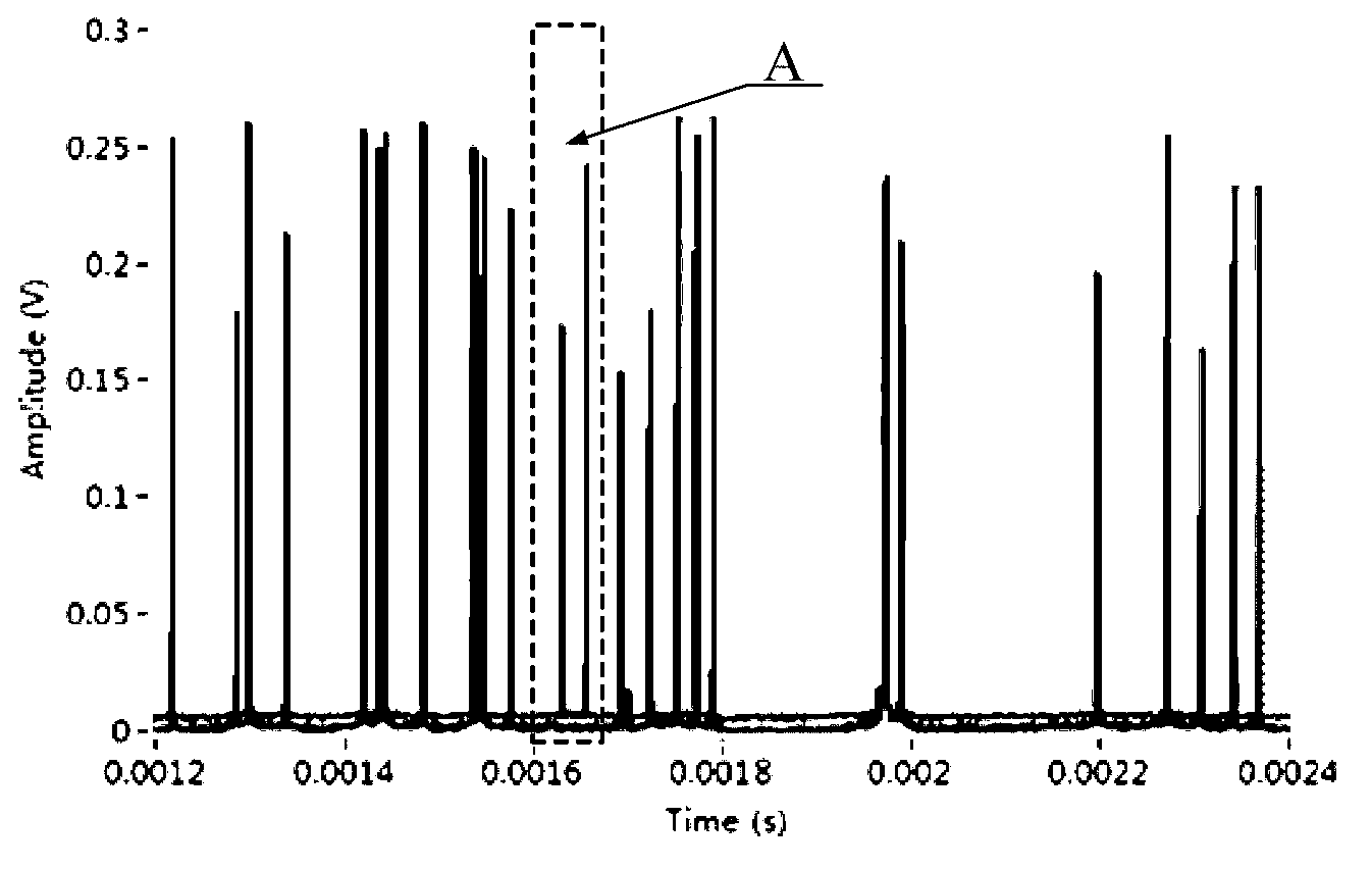
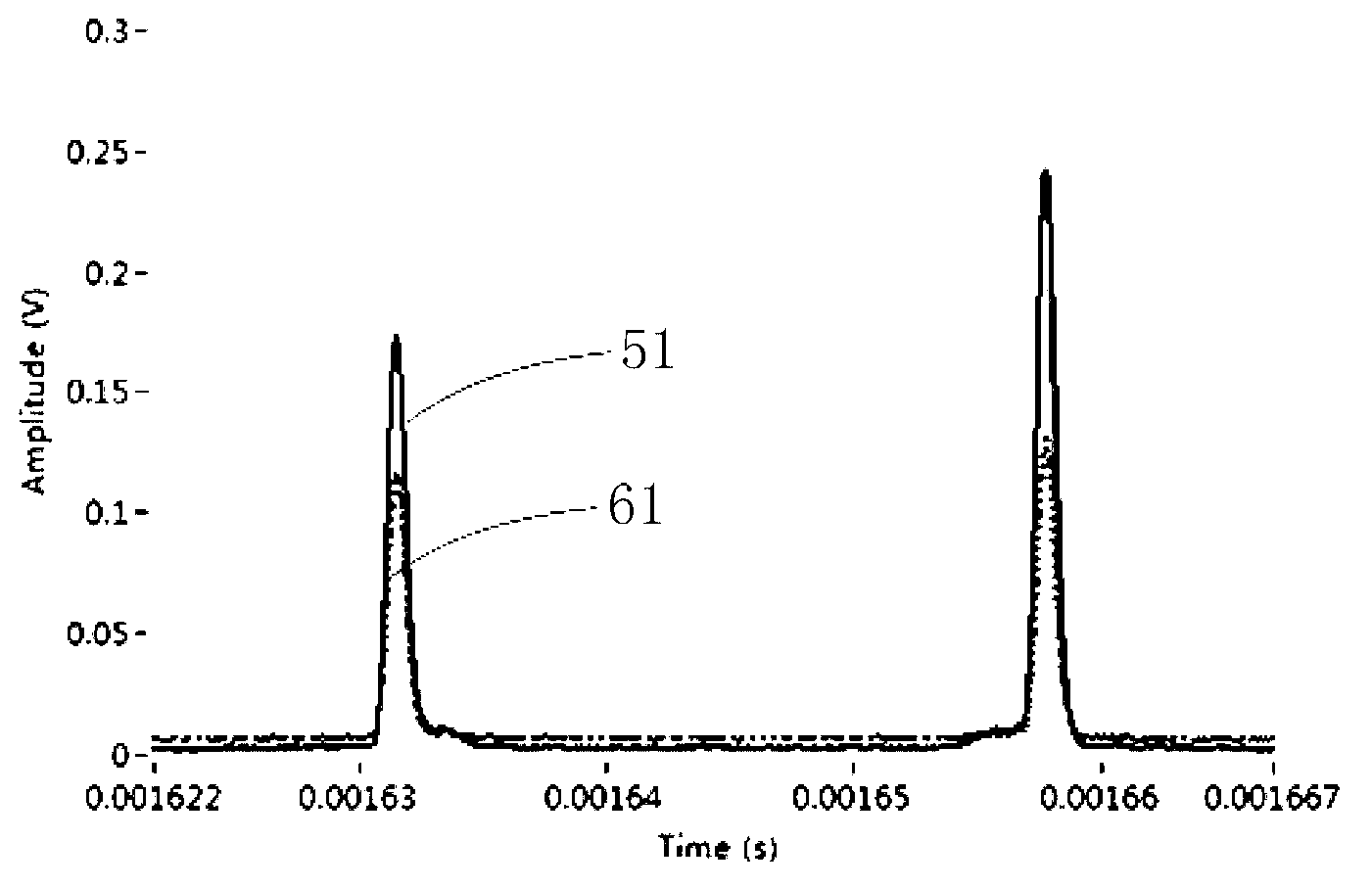
The invention relates to the technical field of cytobiology, and in particular relates to a photoelectric signal peak value detection method and device for a flow cytometer, and the flow cytometer. According to the method and the device, later appearing peak value points can be judged after a peak value point is determined according to an uplink threshold value, a downlink threshold value and a peak value threshold value by setting the uplink threshold value, the downlink threshold value and the peak value threshold value instead of zeroing signals from external input; furthermore, a peak value delay can be conveniently obtained, and the moment that the peak value point appears can be inferred from the peak value delay. Therefore, the device can quickly and precisely judge the peak value point and supply the moment that the peak value point appears, so that basis is supplied to cell subset classification and time delay charging and screening of the flow cytometer. Moreover, compared with a conventional method based on micro processing units such as a singlechip and a digital signal processor (DSP), the photoelectric signal peak value detection method for the flow cytometer based on a field programmable logic gate array has the advantages that the programming difficulty is lower, the calculating speed is higher, and the operation is more stable.

Description

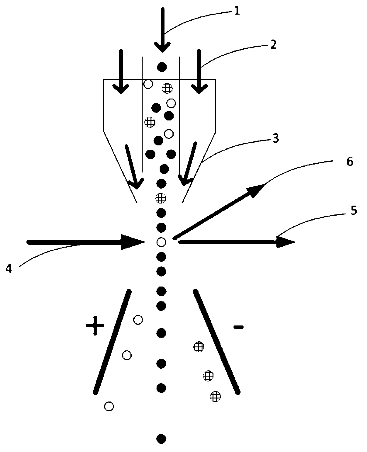
technical field [0001] The invention relates to the technical field of cell biology, in particular to a flow cytometer photoelectric signal peak detection method, a flow cytometer photoelectric signal peak detection device and a flow cytometer using the flow cytometer photoelectric signal peak detection device. Background technique [0002] Flow cytometry is a device for automatic analysis and sorting of cells. It can quickly measure, store and display a series of important biophysical and biochemical characteristic parameters of dispersed cells suspended in liquid, and can sort out specified cell subpopulations according to the pre-selected parameter range. [0003] Such as figure 1 The workflow of the flow cytometer shown in , mainly includes: the sample 1 to be tested is made into a single-cell suspension after the cells to be tested are stained, and then the sample 1 to be tested is pressed into the flow chamber under a certain pressure. The phosphate-buffered sheath f...

Claims


Application Information

Patent Timeline
Patent Type & Authority Applications(China)
IPC IPC(8): G01N15/14G01N21/47
Inventor 朱茜
Owner 青岛爱德生物科技发展基金企业(普通合伙)
Learn More