Control method of automatic control device and device
A control method and equipment technology, applied in sequence/logic controller program control, electrical program control and other directions, can solve problems such as easy occurrence of dangerous accidents, affecting the working performance of automatic control equipment, and large errors in visible light information.
- Summary
- Abstract
- Description
- Claims
- Application Information
AI Technical Summary
Problems solved by technology
Method used
Image
Examples
Embodiment 1
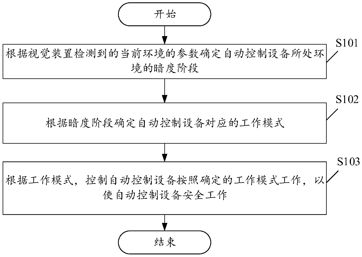
[0079] see figure 1 , figure 1 It is a schematic flowchart of a control method for an automatic control device provided by an embodiment of the present invention. Among them, such as figure 1 As shown, the control method of the automatic control device may include the following steps:
[0080] S101. Determine the darkness stage of the environment where the automatic control device is located according to the parameters of the current environment detected by the vision device.
[0081] In the embodiment of the present application, the dark stage may be a dark stage or a bright stage, which is not limited in this embodiment.
[0082] In the embodiment of the present application, the automatic control device may be an unmanned agricultural machine, an unmanned aerial vehicle, an unmanned driving device, etc., which is not limited in this embodiment.
[0083] In the embodiment of this application, the darkness stage can be pre-configured and stored, and the preset darkness sta...
Embodiment 2
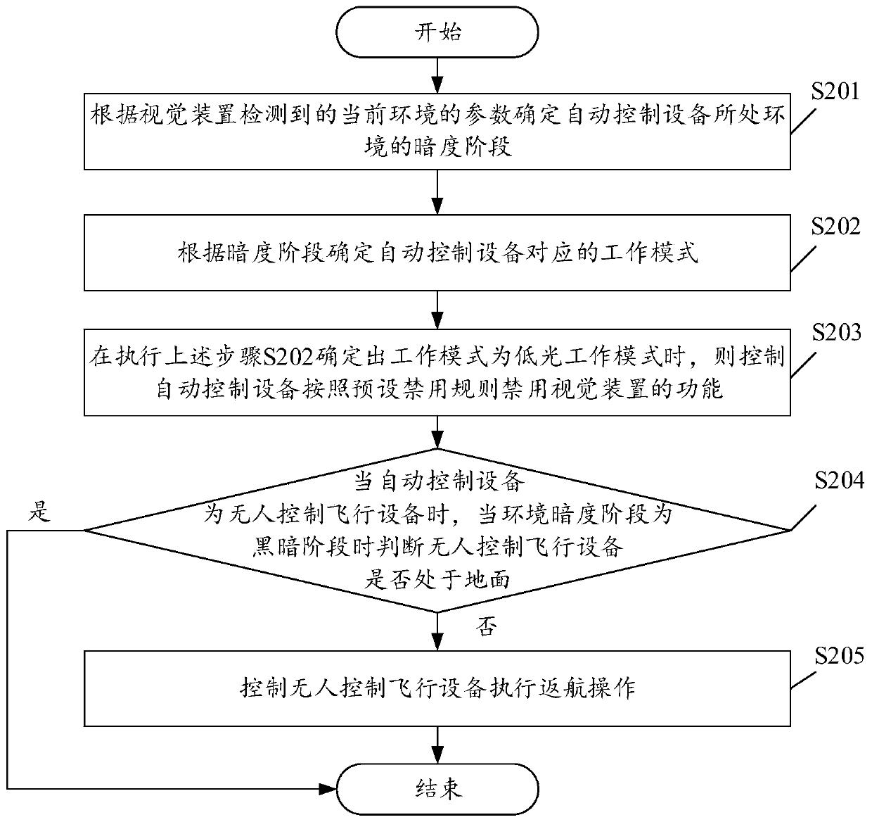
[0112] see figure 2 , figure 2 It is a schematic flowchart of a control method for an automatic control device provided by an embodiment of the present invention. Among them, such as figure 2 As shown, the control method of the automatic control device may include the following steps:
[0113] S201. Determine the darkness stage of the environment where the automatic control device is located according to the parameters of the current environment detected by the vision device.
[0114] In the embodiment of the present application, the dark stage is one of a dark stage, a bright stage, and a low light stage.
[0115] As a further optional implementation manner, determining the darkness stage of the environment where the automatic control device is located according to the parameters of the current environment detected by the visual device may include the following steps:
[0116] judging whether the ambient light intensity detected by the visual device is less than a pres...
Embodiment 3
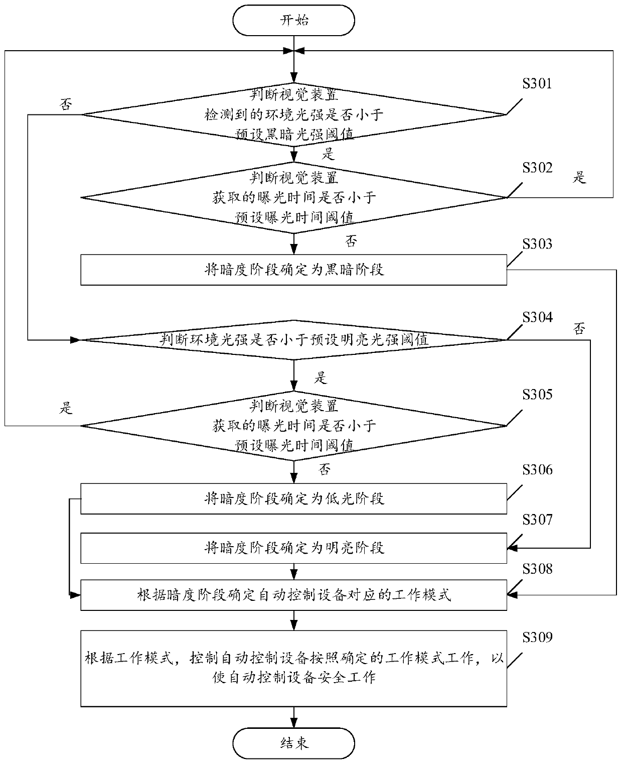
[0162] see image 3 , image 3 It is a schematic flowchart of a control method for an automatic control device provided by an embodiment of the present invention. Among them, such as image 3 As shown, the control equipment of the automatic control equipment may include the following steps:
[0163] S301. Determine whether the ambient light intensity detected by the vision device is less than a preset dark light intensity threshold, if less, perform step S302; if not, perform step S304.
[0164] In the embodiment of the present application, the parameters include the ambient light intensity of the environment where the automatic control device is currently located and the exposure time acquired by the vision device.
[0165] In the embodiment of the present application, each darkness stage has a corresponding light intensity threshold interval. The automatic control device can determine the darkness stage of the environment where the automatic control device is currently l...
PUM
 Abstract
Description
Claims
Application Information
 - R&D
- Intellectual Property
- Life Sciences
- Materials
- Tech Scout
- Unparalleled Data Quality
- Higher Quality Content
- 60% Fewer Hallucinations
Browse by: Latest US Patents, China's latest patents, Technical Efficacy Thesaurus, Application Domain, Technology Topic, Popular Technical Reports.
© 2025 PatSnap. All rights reserved.Legal|Privacy policy|Modern Slavery Act Transparency Statement|Sitemap|About US| Contact US: help@patsnap.com


