Traveling wave tube slow wave system and traveling wave tube comprising same, and traveling wave tube transceiver module

A technology of slow wave system and transceiver components, applied in the direction of traveling wave tubes, circuit components of time-of-flight tubes, etc., can solve the problems of reducing the overall performance of T/R components, limiting applications, poor isolation, etc., to improve the system Performance and reliability, system anti-interference ability enhancement, and the effect of reducing production costs

Active Publication Date: 2019-08-06
NO 12 RES INST OF CETC
View PDF4 Cites 2 Cited by
  • Summary
  • Abstract
  • Description
  • Claims
  • Application Information

AI Technical Summary

Problems solved by technology

However, the T/R high-power switching device reduces the overall performance of the T/R component due to its large insertion loss, slow resp

Method used


Image

  • Traveling wave tube slow wave system and traveling wave tube comprising same, and traveling wave tube transceiver module
  • Traveling wave tube slow wave system and traveling wave tube comprising same, and traveling wave tube transceiver module
  • Traveling wave tube slow wave system and traveling wave tube comprising same, and traveling wave tube transceiver module

Examples


Embodiment Construction

[0035] In order to illustrate the present invention more clearly, the present invention will be further described below in conjunction with preferred embodiments and accompanying drawings. Similar parts in the figures are denoted by the same reference numerals. Those skilled in the art should understand that the content specifically described below is illustrative rather than restrictive, and should not limit the protection scope of the present invention.

[0036] In the following description, for purposes of explanation, numerous specific details are set forth in order to provide a thorough understanding of one or more embodiments. It may be evident, however, that these embodiments may be practiced without these specific details.

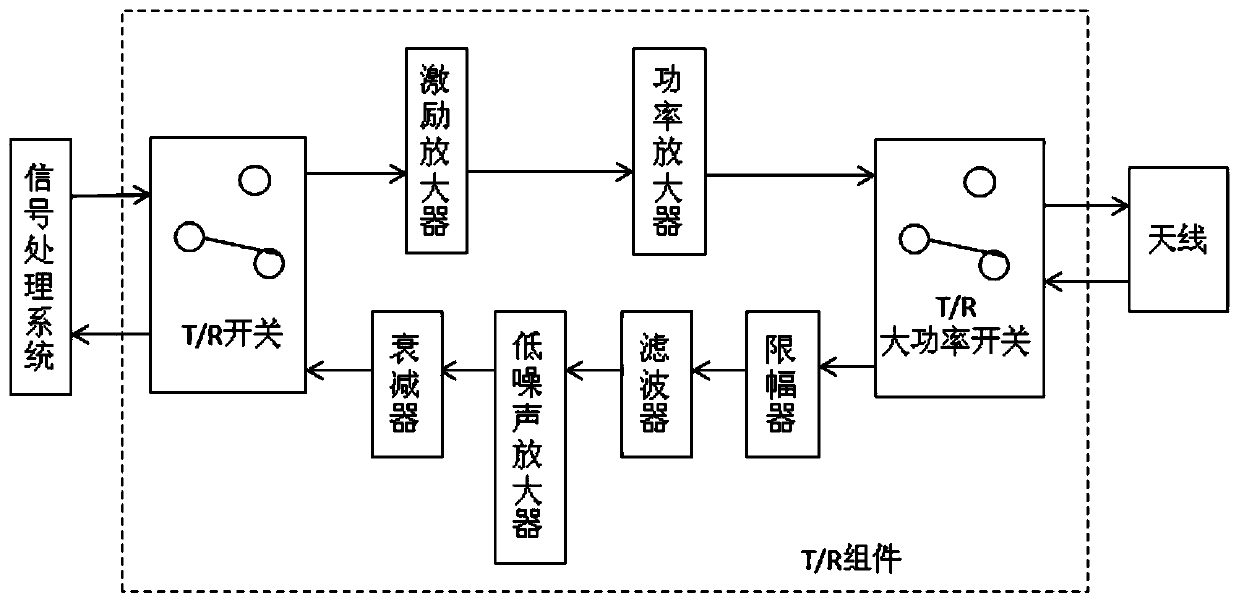
[0037] Figure 1-2 A schematic diagram showing the structure of the T / R assembly and the traveling wave tube in the prior art, the T / R assembly of the prior art is integrated with a T / R switch for coupling with a signal processing system and a T / ...


PUM


Abstract

The invention discloses a traveling wave tube slow wave system and a traveling wave tube comprising the same, and a traveling wave tube transceiver module. The slow wave system includes a spiral line,a first port used for inputting a signal to be amplified, a second port used for outputting the amplified signal and receiving an antenna return signal, and a third port used for outputting the received signal, wherein the ports are coupled to the spiral line, and the third port is arranged between the first port and the second port and near the first port. Compared with the traveling wave tube slow wave system containing two energy transmission ports in the prior art, the traveling wave tube slow wave system provided by the invention is additionally provided with a received signal output port, the signal transmitting and receiving function of the traveling wave tube can be achieved, the cascade structure of the existing T/R module is simplified, the miniaturization of information processing equipment is promoted, and the production cost is reduced. Moreover, the influence of the performance limitation of high-power switches on the whole system is avoided, and the system performance and reliability are improved.

Description

technical field [0001] The invention relates to the technical field of microwave vacuum electronics. More specifically, it relates to a traveling wave tube slow wave system, a traveling wave tube including the traveling wave tube, and a traveling wave tube transceiver assembly. Background technique [0002] The transmitting / receiving component (T / R component) is an indispensable core component in the phased array radar system, and the T / R component plays a key role in the performance and reliability of the entire system. The T / R component not only has the power amplification function of the transmitted signal, but also has the amplification and return of the received signal. As an electric vacuum device with radio frequency power amplification function, the traveling wave tube is usually used in the transmitting unit of the T / R module as the final power amplification. [0003] T / R components composed of traveling wave tubes in the prior art, such as figure 1 As shown, it ...

Claims


Application Information

Patent Timeline
IPC IPC(8): H01J23/27H01J25/36
CPCH01J23/27H01J25/36
Inventor 干媛魏义学孟晓君张宏志任卫宏王伟张雪利刘飞曾爽
Owner NO 12 RES INST OF CETC
Why Eureka
Try Eureka