Anti-off mechanism for new energy automobile charging

A new energy vehicle, vehicle charging technology, applied in electric vehicle charging technology, charging station, electric vehicle and other directions, can solve the problems of low safety, low operation difficulty, inconvenient operation of locking mechanism, etc., to improve safety, increase Contact area, good power transmission effect

Active Publication Date: 2019-08-06
宁波均胜新能源汽车技术有限公司 +1
View PDF8 Cites 4 Cited by
  • Summary
  • Abstract
  • Description
  • Claims
  • Application Information

AI Technical Summary

Problems solved by technology

[0006] The purpose of the present invention is to provide a new energy vehicle charging anti-falling mechanism with high safety and low operation difficulty in order to solve the problems of low safety and inconvenient operation of the locking mechanism during the use of the existing charging gun

Method used


Image

  • Anti-off mechanism for new energy automobile charging
  • Anti-off mechanism for new energy automobile charging
  • Anti-off mechanism for new energy automobile charging

Examples


Embodiment 1

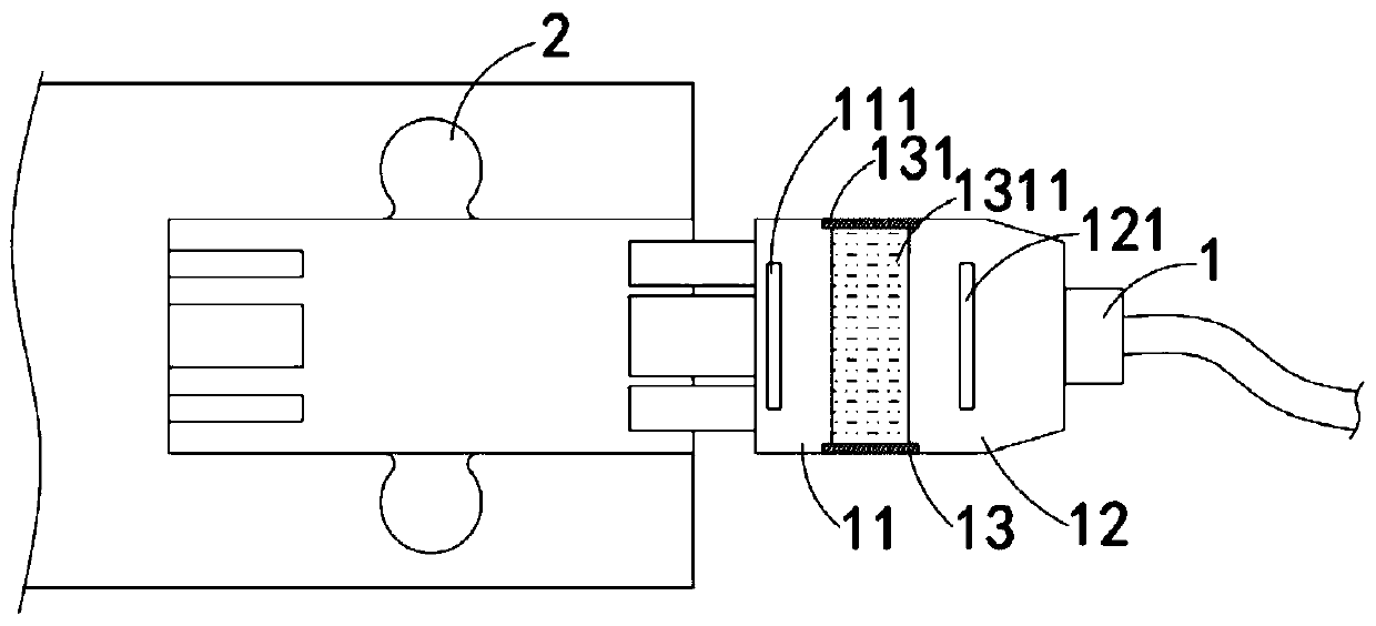
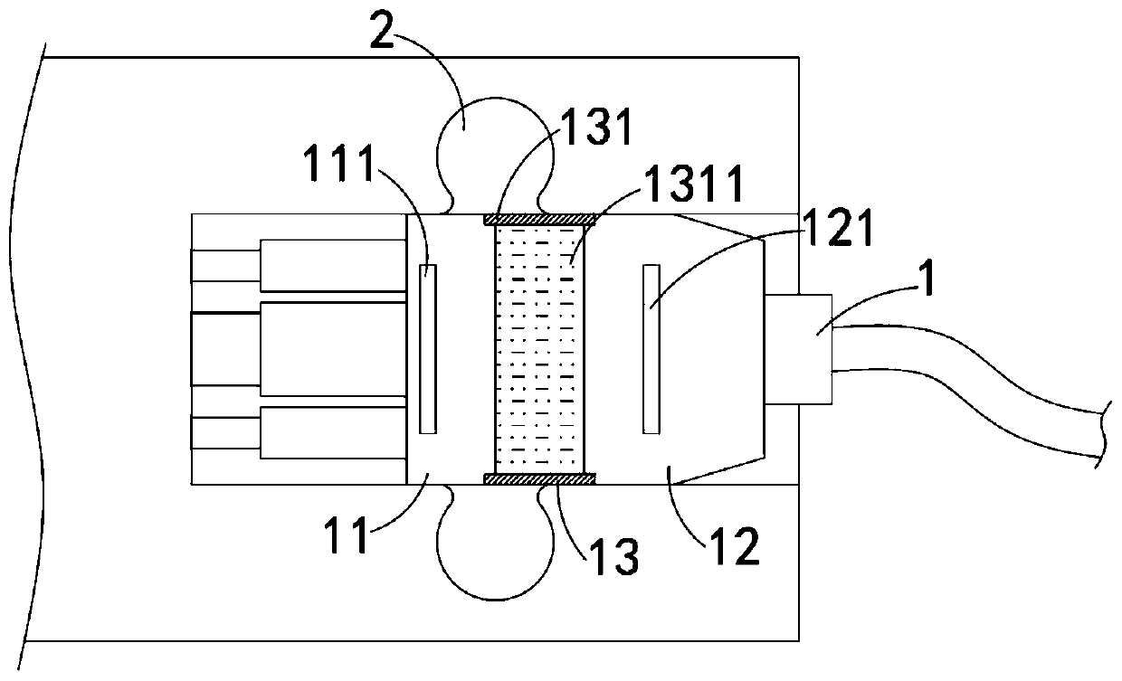
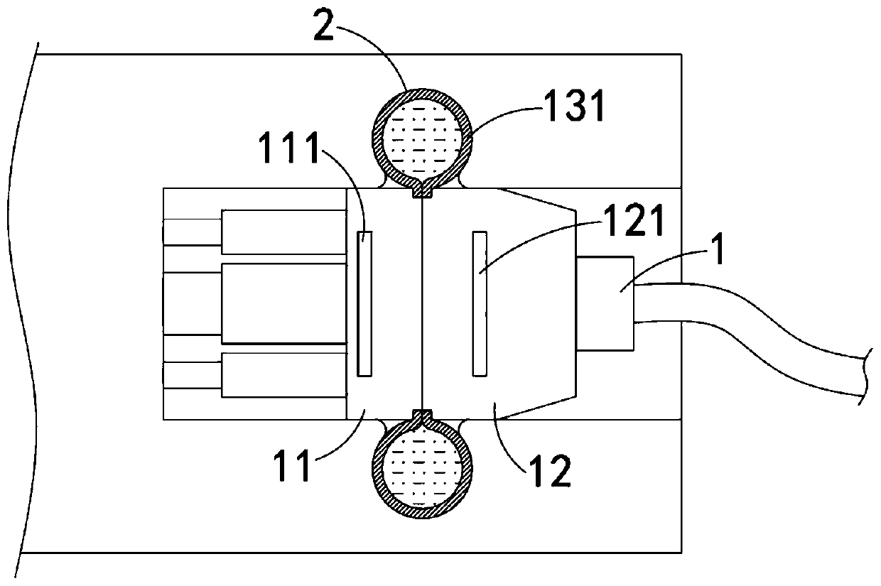
[0031] Such as Figure 1-3 As shown, a new energy vehicle charging anti-falling mechanism includes a charging head 1 and a limit groove 2 arranged in the charging port of the car. The charging head 1 includes:

[0032] The conductive head 11, the front end of the conductive head 11 is provided with a plug, the charging port of the car is provided with a corresponding plug rod, the rear end of the conductive head 11 is the first conductive surface, and the conductive head 11 is embedded with a first permanent magnet. sheet 111;

[0033] Hold the head 12, the rear end of the hold head 12 is electrically connected to the external power line, the front end of the hold head 12 is the second conductive surface, and the first conductive surface and the second conductive surface are passed between the conductive head 11 and the hold head 12. The contact between the conductive surfaces realizes power transmission, and the holding head 12 is embedded with a second permanent magnet piec...

Embodiment 2

[0040] Such as Figure 4 As shown, the difference between this embodiment and embodiment 1 is that: the first conductive surface is a convex arc surface, the second conductive surface is a concave arc surface, and the first conductive surface and the second conductive surface match.

[0041] In this embodiment, in the process of moving the second conductive surface to the first conductive surface, it is easier to squeeze the insulating liquid into the elastic connecting cylinder 131. At the same time, since the first conductive surface and the second conductive surface are arc-shaped, The contact area is increased to improve the stability of power transmission.

Embodiment 3

[0043] Such as Figure 5-7 As shown, the difference between this embodiment and Embodiment 1 is that a cooling groove is provided on the second conductive surface, an elastic disc 14 is fixedly installed in the cooling groove, and a plurality of guide holes are evenly distributed on the elastic disc 14 141. The elastic disc 14 is made of two-way memory alloy, and its transformation temperature is 60°C. When the temperature is lower than 60°C, the low-temperature phase of the elastic disc 14 is concave and adheres to the side wall of the cooling tank. It needs to be explained What is more important is that the conductive part is located on the side wall of the cooling tank, and the conductive area is smaller than the side wall area of ​​the cooling tank, only when the elastic disc 14 is completely attached to the cooling tank, can the conduction of the circuit be realized; When the temperature is higher than 60°C, the high-temperature phase of the elastic disc 14 is convex and ...


PUM


Abstract

The invention belongs to the field of new energy automobiles, and particularly relates to an anti-off mechanism for new energy automobile charging. The anti-off mechanism includes a charging head anda limit slot arranged in an automobile charging port. The charging head includes a conductive head and a grip head. The conductive head is provided with a plug at the front end, the back end of the conductive head is a first conductive surface, and a first permanent magnet piece is embedded into the conductive head. The back end of the grip head is electrically connected with an external power line, and the front end of the grip head is a second conductive surface. Power transmission between the conductive head and the grip head is realized through the contact between the first conductive surface and the second conductive surface. A second permanent magnet piece is embedded into the grid head. The first permanent magnet piece and the second permanent magnet piece attract each other becauseof opposite poles. The conductive head and the grip head are connected by a connector. The safety of the charging gun in the use process can be improved. An overheating protection mechanism is arranged, which not only can prolong the service life of the charging gun, but also can reduce the occurrence of accidents caused by overheating.

Description

technical field [0001] The invention belongs to the field of new energy vehicles, and in particular relates to a new energy vehicle charging drop-off prevention mechanism. Background technique [0002] New energy vehicles refer to the use of unconventional vehicle fuels as a power source, which can reduce the consumption of petroleum resources and reduce pollutant emissions. Among them, pure electric vehicles are the most widely promoted. [0003] When charging a new energy vehicle, it is usually necessary to use a charging gun for charging. When the charging gun is inserted into the charging stand, its conductive end is exposed, which is prone to electric shock accidents; in addition, the existing charging gun is used During the process, it is easy to fall off, which further increases the risk of using the charging gun. In addition, the existing charging gun and the charging stand are usually locked and locked by a mechanical locking mechanism, which is not only cumbersome ...

Claims


Application Information

Patent Timeline
IPC IPC(8): H01R13/02H01R13/502H01R13/627H01R13/71H01R13/713B60L53/16B60L53/302
CPCB60L53/16B60L53/302H01R13/02H01R13/502H01R13/6277H01R13/71H01R13/7137H01R2201/26Y02T10/70Y02T10/7072Y02T90/12Y02T90/14
Inventor 陈昌义
Owner 宁波均胜新能源汽车技术有限公司
Why Eureka
Try Eureka