
Air cushion bed

A technology of air bed and inflatable chamber, which is applied in the field of air bed, and can solve the problems of limited effect of the air bed and reduction of the use effect of the air bed

Pending Publication Date: 2019-08-09
INTEX OPTOELECTRONICS XIAMEN CO LTD
View PDF1 Cites 3 Cited by
  • Summary
  • Abstract
  • Description
  • Claims
  • Application Information

AI Technical Summary

Problems solved by technology

[0004] The above existing technical solutions have the following defects: During the use of the air bed, the top surface of the air bed is in contact with the human body to provide comfortable support for the human body, so the top surface of the air bed is required to have a certain degree of elasticity and stretching effect In order to ensure comfort; the surrounding side of the air mattress mainly plays a role in supporting the overall shape and structure of the air mattress, so the peripheral side of the air mattress is required to have good tensile properties to ensure the support of the air mattress
The mattress body of the existing air bed usually adopts the way of integral material molding, that is, the material of the top surface of the air bed is the same as that of the side and bottom of the air bed, and because the functions of different parts of the air bed are different, the side of the air bed is different. The effect of the air bed is opposite to that of the top surface of the air bed. Using the same material makes the effect of each part of the air bed structure limited, reducing the overall use of the air bed.

Method used


Image

  • Air cushion bed
  • Air cushion bed
  • Air cushion bed

Examples


Embodiment 1

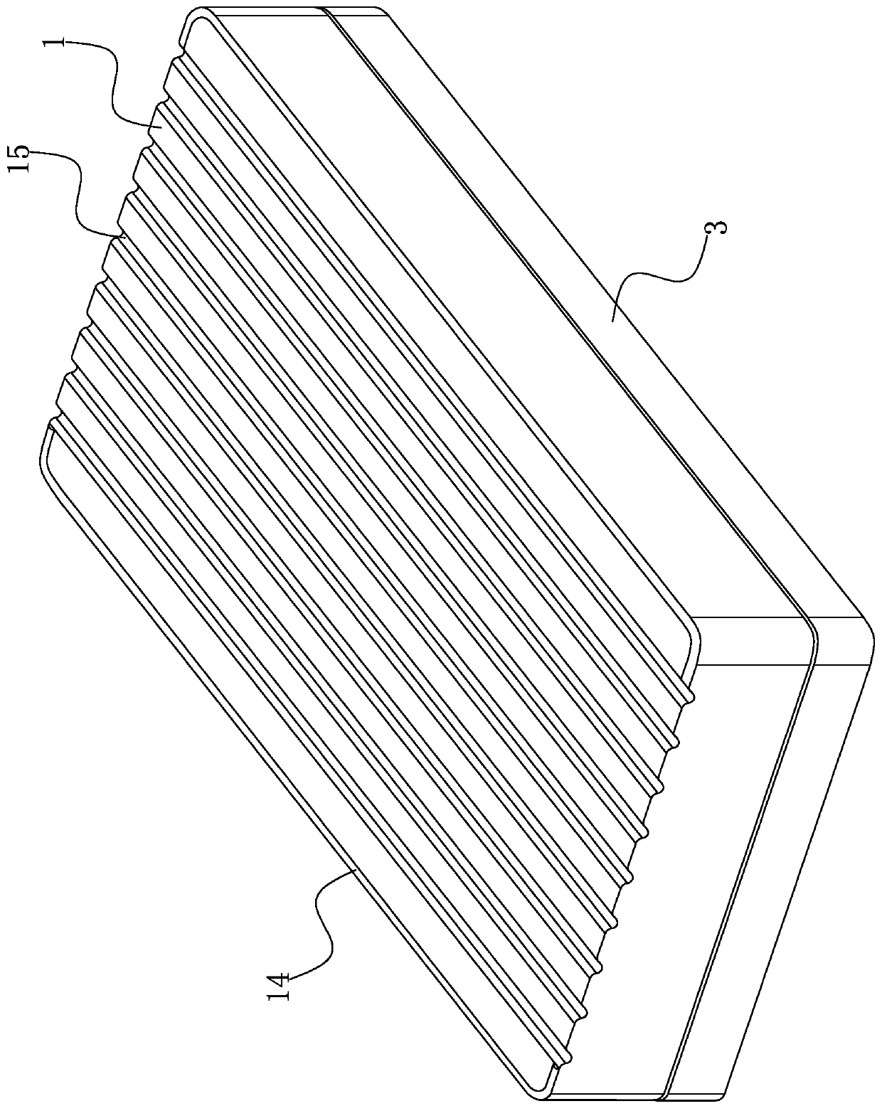
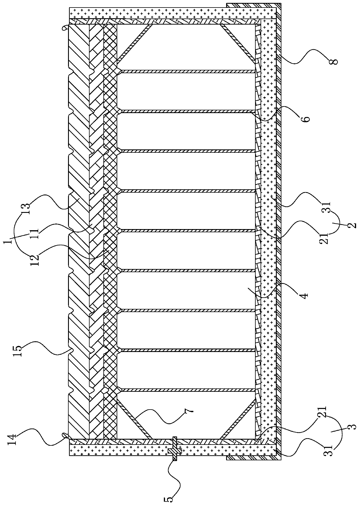
[0038] The invention discloses an air bed, such as figure 1 , 2 As shown in , 2A, it includes an upper piece 1 and a lower piece 2 arranged at intervals and a flexible shroud 3 located between the upper piece 1 and the lower piece 2 to surround and fix the outer peripheral side. The upper piece 1, the lower piece 2 and the shroud 3 form a closed inflatable chamber 4, the surface of the shroud 3 is fixed with an inflatable head 5 connected to the inflatable chamber 4, and a number of main limit pulls are connected between the upper piece 1 and the lower piece 2 The belt 6 and the upper sheet 1 include a bonded and fixed supporting fiber layer 11 and an elastic polymer layer 12 , and the shroud 3 and the lower sheet 2 both include a plain weave fabric layer 31 .

[0039] like figure 1As shown, in the present embodiment, the upper sheet 1 and the lower sheet 2 are all cut into rectangular cloth pieces, and the shroud 3 is in the shape of a rectangular surface. The shape and siz...

Embodiment 2

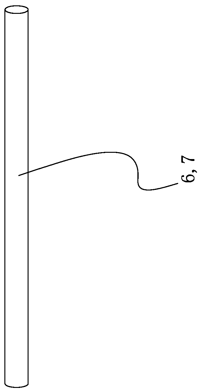
[0044] The invention discloses an air bed, such as image 3 , 3A , 3B, including the upper sheet 1 bonded by the flannelette layer 13, the supporting fiber layer 11 and the elastic polymer layer 12, the lower sheet 2 and the surrounding sheet composed of the plain fabric layer 31 and the polymer airtight layer 21 Belt 3, the difference between this embodiment and Embodiment 1 is that: the main limit drawstring 6 and the auxiliary limit drawstring 7 are set in a flat wide sheet shape, and it is connected with the upper piece 1, the lower piece 2 and the surrounding belt 3 The connecting end faces between them are rectangular faces.

Embodiment 3

[0046] The invention discloses an air bed, such as Figure 4 , 4A As shown, it includes an upper sheet 1 bonded by a flannelette layer 13, a support fiber layer 11 and an elastic polymer layer 12, a lower sheet 2 and a girdle 3 composed of a plain weave fabric layer 31 and a polymer airtight layer 21 , which is different from Embodiment 2 in that: the main limit drawstring 6 and the auxiliary limit drawstring 7 are in the shape of a column surrounded by a wide band, and it is connected with the upper piece 1, the lower piece 2 and the surrounding belt 3. Connect the end faces into a torus.

[0047] The use process and beneficial effects of the present invention are as follows: when using the air bed of the present invention, the air bed is inflated by connecting an inflatable device such as an air pump to the inflatable head 5, and the inflatable chamber 4 is inflated and expanded between the main limit drawstring 6 and the auxiliary limit Shaped under the position-limiting ...


PUM


Abstract

The invention discloses an air cushion bed, and relates to the technical field of inflatable products. The technical problem that the overall use effect of the air cushion bed is reduced by using thesame forming material to produce an air cushion bed body is solved. The air cushion bed is technically characterized by comprises an upper piece, a lower piece and a flexible surrounding belt, the upper piece and lower piece are arranged at an interval, the flexible surrounding belt is fixedly located on the peripheral side between the upper piece and the lower piece, and a sealed inflation chamber is formed by the upper piece, the lower piece and the flexible surrounding belt; an inflating head communicated with the inflation chamber is fixed to the surface of the surrounding belt, and a plurality of main limiting pull belts are connected between the upper piece and the lower piece; the upper piece comprises a support fiber layer and an elastic polymer layer which are bonded and fixed together, and the elastic polymer layer is located on the side, close to the inflation chamber, of the support fiber layer; the surrounding belt and the lower piece both comprise a plain weave fabric layer, the elasticity of the elastic polymer layer is larger than that of the support fiber layer, and the elasticity of the support fiber layer is larger than that of the plain weave fabric layer. The air cushion bed has the advantage of improving the overall use effect of the air cushion bed.

Description

technical field [0001] The invention relates to the technical field of inflatable products, more specifically, it relates to an air bed. Background technique [0002] A Chinese patent with publication number CN108618467A discloses a highly air-permeable air bed and its manufacturing method, comprising a mattress body with a cavity inside, and a wear-resistant layer attached to the side of the mattress body; Both the upper surface and the lower surface of the mattress body have a number of arc-shaped protrusions, air passages are formed between adjacent protrusions, and the air passages have non-slip brushed lines. The upper surface of the mattress body also has An inflatable head is provided. [0003] In the prior art, the air mattress described above generally includes a mattress body with an inflatable head and an inflatable chamber located in the mattress body and connected to the inflatable head. The inflatable chamber is inflated through the inflatable head to make the...

Claims


Application Information

Patent Timeline
IPC IPC(8): A47C27/08A47C27/12A47C27/00A47C17/86
CPCA47C27/081A47C27/087A47C27/088A47C27/12A47C27/124A47C27/00A47C17/86
Inventor 刘荣隆
Owner INTEX OPTOELECTRONICS XIAMEN CO LTD
Learn More