Hydraulic pump spindle positioning assembly and hydraulic pump spindle machining device

A positioning component and spindle processing technology, applied in positioning devices, metal processing equipment, metal processing mechanical parts, etc., can solve the problems of low processing efficiency of hydraulic pump spindles, and achieve the effect of improving processing efficiency

Pending Publication Date: 2019-08-09
杭州力龙液压有限公司
View PDF0 Cites 0 Cited by
  • Summary
  • Abstract
  • Description
  • Claims
  • Application Information

AI Technical Summary

Problems solved by technology

[0005] The purpose of the present invention is to provide a hydraulic pump spindle positioning tool and a hydraulic pump spindle processing device to solve the technical problem of low processing efficiency of the hydraulic pump spindle in the prior art

Method used


Image

  • Hydraulic pump spindle positioning assembly and hydraulic pump spindle machining device
  • Hydraulic pump spindle positioning assembly and hydraulic pump spindle machining device
  • Hydraulic pump spindle positioning assembly and hydraulic pump spindle machining device

Examples


Embodiment Construction

[0025] It should be noted that, in the case of no conflict, the embodiments of the present invention and the features in the embodiments can be combined with each other. The present invention will be described in detail below with reference to the accompanying drawings and examples.

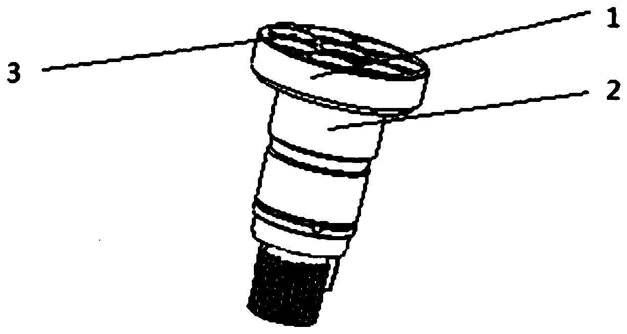
[0026] It should be noted that the hole to be processed is set on the end surface of the head shaft of the main shaft away from the bottom shaft. The diameter of the head shaft is larger than the diameter of the bottom shaft, so that the two form a T-shaped structure, and a shaft shoulder.

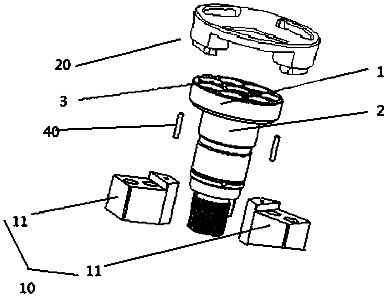
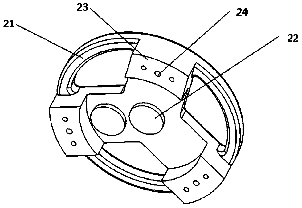
[0027] like figure 2 and image 3 As shown, the present invention provides a hydraulic pump spindle positioning assembly, comprising: a first positioning member 10 and a second positioning member 20 that are detachably connected to each other; the first positioning member 10 is fixed on the chuck, and the first positioning member 10 is used for On the side of the supporting spindle away from the hole to b...


PUM


Abstract

The invention relates to the technical field of machining tools, in particular to a hydraulic pump spindle positioning assembly and a hydraulic pump spindle machining device. The hydraulic pump spindle positioning assembly comprises a first positioning piece and a second positioning piece which are detachably connected with each other, the first positioning piece is fixed on a chuck, the first positioning piece is used for supporting one side, far away from a to-be-machined hole, of the spindle, and a gap exists between the first positioning piece and the side wall on one side; and the secondpositioning piece comprises a base body and at least two positioning parts arranged on the base body, and the positioning parts are used for forming pin hole positioning with the to-be-machined hole in the spindle. According to the hydraulic pump spindle positioning assembly, tool setting can be performed before a first ball socket is machined, the tool setting does not need to be repeated, and the machining efficiency is improved.

Description

technical field [0001] The invention relates to the technical field of machining tools, in particular to a hydraulic pump spindle positioning assembly and a hydraulic pump spindle processing device. Background technique [0002] like figure 1 As shown, the main shaft of the hydraulic pump generally includes a horizontally extending head shaft and a longitudinally extending bottom shaft. The head shaft 1 and the bottom shaft 2 form a T shape. The center of the head shaft 1 is provided with a central hole. A plurality of blind holes centered on the central hole are distributed on the surface of the shaft column 1 . Both the central hole and the blind hole are ball-and-socket structures. [0003] Ball socket processing is the core process of hydraulic pump spindle processing. In order to quickly locate the processing position of the ball socket during the processing process, usually before processing the ball socket, the hole to be processed is pre-machined on the end surface...

Claims


Application Information

Patent Timeline
IPC IPC(8): B23Q3/12B23B31/12
CPCB23Q3/12B23B31/12
Inventor 曹国丰苏闯南吴新锋
Owner 杭州力龙液压有限公司
Why Eureka
Try Eureka