Portable ejection mechanism for storage battery mold

A convenient ejection mechanism technology, which is applied in the field of portable ejection mechanism for battery molds, can solve the problems of uniform force on the mold, ejection of molds that cannot be formed, and lower quality of forming molds, etc., to achieve uniform force , Safe and convenient to use, and the effect of improving stability

Inactive Publication Date: 2019-08-09
CHANGXING QIKAI MECHANICAL EQUIP CO LTD
View PDF1 Cites 0 Cited by
  • Summary
  • Abstract
  • Description
  • Claims
  • Application Information

AI Technical Summary

Problems solved by technology

[0004] The present invention provides a convenient ejection mechanism for a battery mold, which can effectively solve the problem that the traditional mold ejection mechanism proposed in the above background technology has a complex structure, cumbersome operation, and cannot promptly and effectively eject the molded mold. Secondly, the traditional When the mold ejection structure ejects the formed mold, it cannot ensure that the bottom of the mold is evenly stressed, so it is easy to cause deformation and damage to the mold when the mold is ejected, thereby reducing the quality of the molding mold.

Method used


Image

  • Portable ejection mechanism for storage battery mold
  • Portable ejection mechanism for storage battery mold
  • Portable ejection mechanism for storage battery mold

Examples


Embodiment Construction

[0023] The preferred embodiments of the present invention will be described below in conjunction with the accompanying drawings. It should be understood that the preferred embodiments described here are only used to illustrate and explain the present invention, and are not intended to limit the present invention.

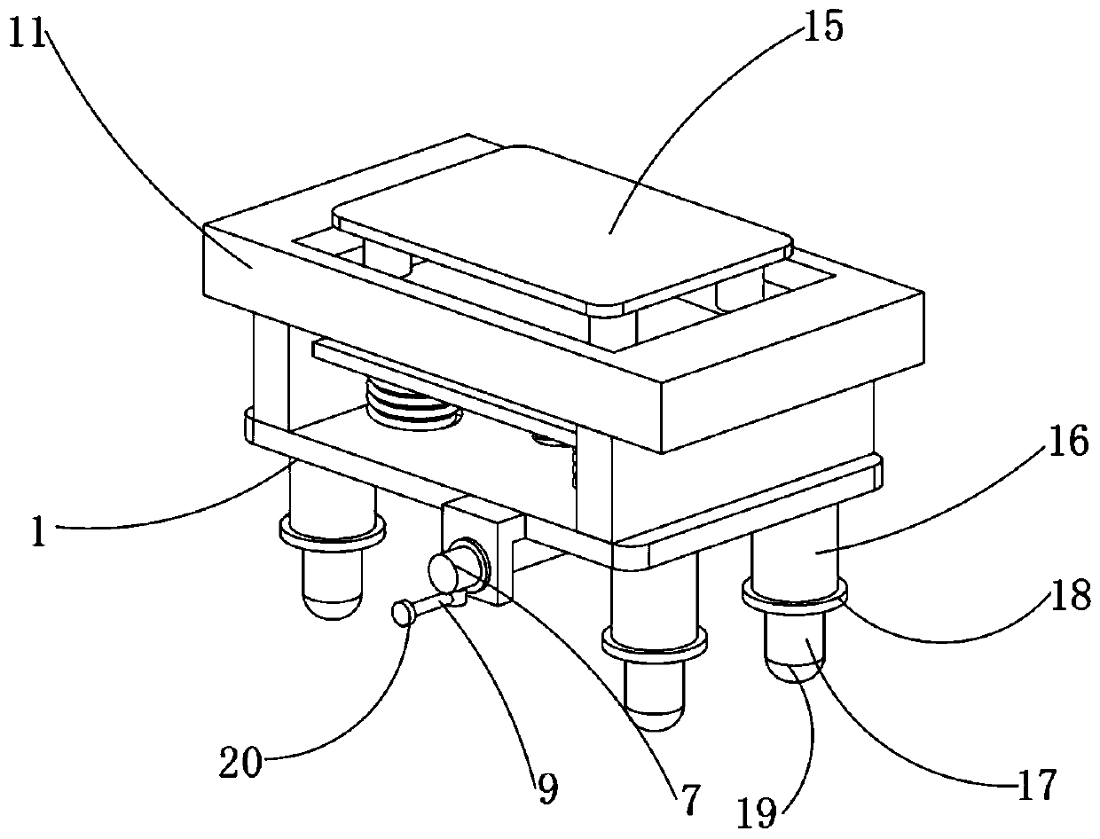
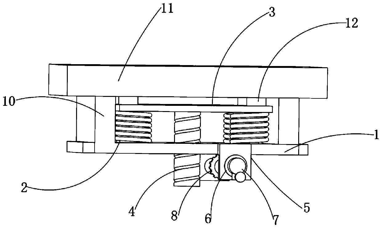
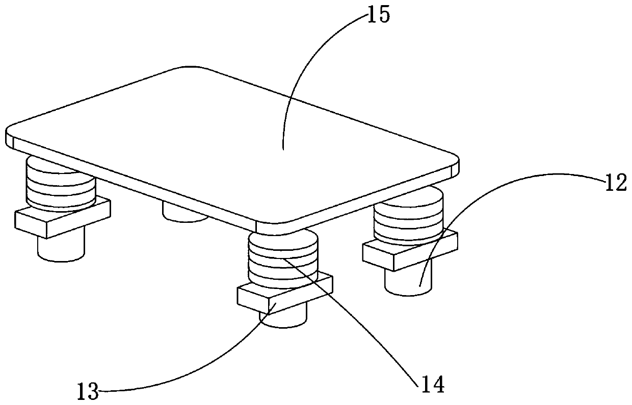
[0024] Example: such as Figure 1-4 As shown, the present invention provides a technical solution, a portable ejection mechanism for battery molds, including a bottom plate 1, and return springs 2 are installed at the four corners of the top of the bottom plate 1, and a support plate 3 is connected to the top of the return spring 2 to support The middle part of the bottom end of the plate 3 is welded with a worm screw 4, and both sides of the bottom plate 1 are welded with a fixed block 5, and the middle parts of one side of the two fixed blocks 5 are embedded with a bearing 6, and a rotating rod 7 is sleeved between the two bearings 6. The outer middle part of the ...


PUM


Abstract

The invention discloses a portable ejection mechanism for storage battery mold. The portable ejection mechanism comprises a bottom plate, wherein reset springs are installed at four corners of the topend of the bottom plate, the top ends of the reset springs are connected with a supporting plate, a worm is welded to the middle of the bottom end of the supporting plate, fixing blocks are welded tothe two sides of the bottom plate, and a bearing is embedded in the middle of one side of the two fixing blocks. The portable ejection mechanism is scientific and reasonable in structure, and safe and convenient to use, the worm can be driven to move upwards through a rotating rod, a bearing, a gear and a crank, and therefore ejector rods at the top end of the supporting plate can be driven to eject the forming mold upwards; the supporting plate can be pulled to move downwards through the reset springs, so that the ejector rods can be reset, the operation is convenient, and the use is convenient; a push plate and the ejector rods are utilized, so that the forming mold in the female mold is stressed uniformly, and damage to the mold due to the top end of the single ejector rod when the ejector rods move upwards is avoided; and the bottom end of the push plate can be buffered through utilizing notches, mounting seats and spring barrels.

Description

technical field [0001] The invention relates to the technical field of molds, in particular to a convenient ejection mechanism for battery molds. Background technique [0002] In today's society, when people produce some mechanical products, they often observe the effect of the product through the injection mold. Facilitate people's next operation; [0003] For example, a Chinese patent discloses a hybrid ejection mechanism for molds (authorized notification number CN 205735716 U). This patented technology uses a combination of a straight line ejection method and an inner oblique ejection method to form a two-stage inner oblique ejection mechanism. , effectively ensure the smooth ejection of the oblique inner product during demoulding, and improve the stability and reliability of the ejection of the inner oblique product. However, the traditional mold ejection mechanism is complex in structure, cumbersome in operation, and cannot be timely Effectively eject the formed mold...

Claims


Application Information

Patent Timeline
Patent Type & Authority Applications(China)
IPC IPC(8): B29C45/40B29L31/34
CPCB29C45/4005B29L2031/3468
Inventor 许胜强
Owner CHANGXING QIKAI MECHANICAL EQUIP CO LTD
Why Eureka
Try Eureka