Intelligent automation isolation pile for highway

An isolation pile, intelligent technology, applied in the direction of roads, roads, road safety devices, etc., can solve the problems of increasing the mechanical fatigue of the connecting plate, unintentional violations, deformation of the connecting plate, etc., to reduce the force-bearing area and avoid energy waste , the effect of reducing wind resistance

Inactive Publication Date: 2019-08-09
魏凡皓
View PDF16 Cites 7 Cited by
  • Summary
  • Abstract
  • Description
  • Claims
  • Application Information

AI Technical Summary

Problems solved by technology

However, these two kinds of isolation piles have different problems. The advantage of the connecting rod type is that the wind resistance is small and it is not easy to be shaken by the wind. The disadvantage is that the connecting rod is easy to be crossed by people, or drilled from the gap between the connecting rods. However; the advantage of the connecting plate type isolation pile is that it is not easy to be crossed by people, but the disadvantage is that the wind resistance is large, especially in spring, autumn, winter and other windy seasons, the force bearing area of ​​the connecting plate facing the wind is relatively large, and the wind will blow The connecting plate shakes and further drives the pile body to shake. On the one hand, it will reduce the firmness of the connection between the pile body and the ground. On the other hand, it will easily increase the mechanical fatigue of the connecting plate, resulting in deformation of the connecting plate. , when the wind blows, the connecting plate fluctuates on one side, which also poses a potential danger to traffic vehicles
[0004] Further, the traffic signs on the road surface of the highway (such as driving direction arrows, speed limit signs, virtual and solid lines of the lane, etc.) often have more traffic and cause the road traffic signs to be unclear. On the one hand, it is easy to induce traffic accidents, and on the one hand it is easy to cause many Drivers also increase the workload of the traffic police department because they cannot see the traffic signs clearly and do not intentionally violate the rules.

Method used


Image

  • Intelligent automation isolation pile for highway
  • Intelligent automation isolation pile for highway
  • Intelligent automation isolation pile for highway

Examples


Embodiment Construction

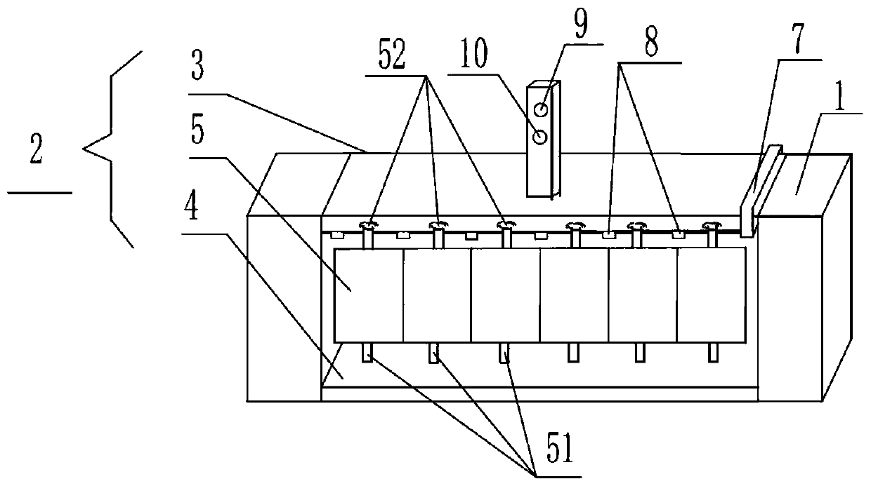
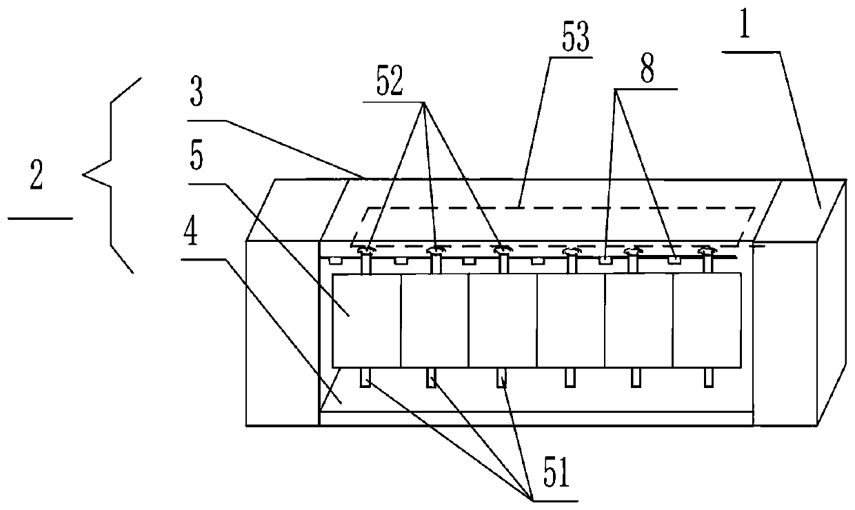
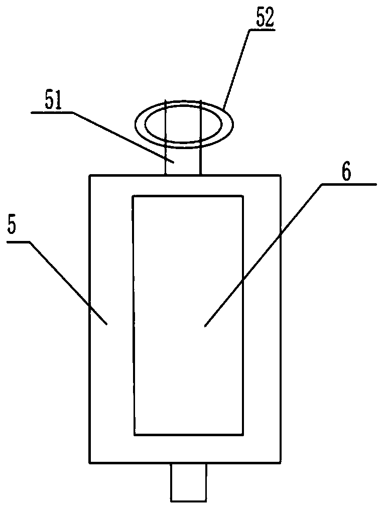
[0021] The present invention will be further described in detail below in conjunction with the accompanying drawings and specific embodiments.

[0022] The isolation piles in the prior art generally adopt connecting rod type isolation piles (such as the isolation pile disclosed in patent CN205822063U), or adopt connection plate type isolation piles, that is, two pile bodies are connected by connecting rods and connecting plates. . However, these two types of isolation piles have different problems. The advantage of the connecting rod type is that the wind resistance is small and it is not easy to be shaken by the wind. The disadvantage is that the connecting rod is easy to be crossed by people, or drilled from the gap between the connecting rod However, the advantage of the connecting plate type isolation pile is that it is not easy to be crossed by people, but the disadvantage is that the wind resistance is large, especially in spring, autumn, winter and other windy seasons, ...


PUM


Abstract

The invention discloses an intelligent automation isolation pile for a highway. The intelligent automation isolation pile for the highway includes pile bodies, a connecting part is arranged between the two adjacent pipe bodies, the connecting part includes an upper supporting beams, a lower supporting beam and shutter slats located between the upper supporting beam and the lower supporting beam, wherein one or more of the upper supporting beam, the lower supporting beam and the pile are provided with anti-collision buffering air bags, and air jet openings are formed in the air bags. Accordingto the intelligent automation isolation pile for the highway, wind resistance can be effectively lowered and automatically adjusted, thus the isolation pile is integrally not prone to shaking, and theair jet openings and a projection device are automatically controlled according to the definition of road surface traffic marks, so that the high definition of the road surface traffic marks are maintained.

Description

technical field [0001] The invention relates to traffic auxiliary facilities, in particular to an automatic intelligent isolation pile for highways. Background technique [0002] Isolation piles are common traffic auxiliary facilities used in highways, residential areas, and gas stations. [0003] The isolation piles that are used for roads in the prior art generally adopt connecting rod-type isolation piles (such as the isolation piles disclosed in patent CN205822063U), or adopt connection plate-type isolation piles, that is, two pile bodies are connected and connected by connecting rods. Use connection plate connection. However, these two types of isolation piles have different problems. The advantage of the connecting rod type is that the wind resistance is small and it is not easy to be shaken by the wind. The disadvantage is that the connecting rod is easy to be crossed by people, or drilled from the gap between the connecting rod However, the advantage of the connect...

Claims


Application Information

Patent Timeline
Patent Type & Authority Applications(China)
IPC IPC(8): E01F15/00
CPCE01F15/00
Inventor 魏凡皓
Owner 魏凡皓
Why Eureka
Try Eureka