Half axle forging forming technology

A forging forming and crafting technology, which is applied in the direction of manufacturing tools, metal processing equipment, forging/pressing/hammer devices, etc., can solve problems such as high equipment cost, increased vehicle cost, and poor flange forming, so as to reduce production Cost, the effect of reducing the cost of the whole vehicle

Active Publication Date: 2014-10-08
JILIN YUANFANG MACHINERY GROUP
View PDF6 Cites 6 Cited by
  • Summary
  • Abstract
  • Description
  • Claims
  • Application Information

AI Technical Summary

Problems solved by technology

When the diameter of the flange exceeds φ240, for example, if a certain model requires φ370mm, the theoretically required equipment tonnage is at least 3000 tons, but our factory only has hydraulic presses with a maximum tonnage of 1250 tons, which far exceeds the limit tonnage of existing equipment. When the pendulum mill is formed, due to the tonnage of the pendulum mill and the pressure that the pendulum bearing can withstand, the flange is not well formed, and the sharp corners of the outer circle of the flange cannot be placed, and there is a lack of meat.
[0005] The cost of choosing large-tonnage equipment is high. Taking the swing head bearing as an example of a 200-ton swing mill, the two bearings are bearing models 29364 (price 7,000 yuan) and 29352 (price 4,000 yuan). If the imported model 29364 bearing is more than 30,000 The bearing is replaced every 2-3 months; if you directly purchase the finished large-diameter flange half shaft (currently imported from the United States), the cost is also high, and the cost of the whole vehicle is increased.

Method used


Image

  • Half axle forging forming technology
  • Half axle forging forming technology
  • Half axle forging forming technology

Examples


Embodiment Construction

[0032] The invention discloses a half-shaft forging molding process, which aims to use a hydraulic press with a smaller tonnage to press a half-shaft with a larger flange diameter, reduce the production cost of half-shaft parts, and further reduce the cost of a complete vehicle.

[0033] The following will clearly and completely describe the technical solutions in the embodiments of the present invention with reference to the accompanying drawings in the embodiments of the present invention. Obviously, the described embodiments are only some, not all, embodiments of the present invention. Based on the embodiments of the present invention, all other embodiments obtained by persons of ordinary skill in the art without making creative efforts belong to the protection scope of the present invention.

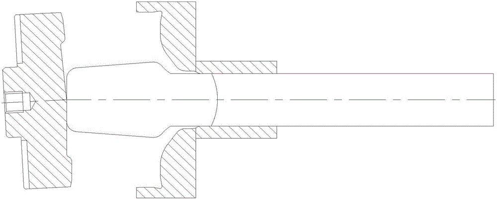
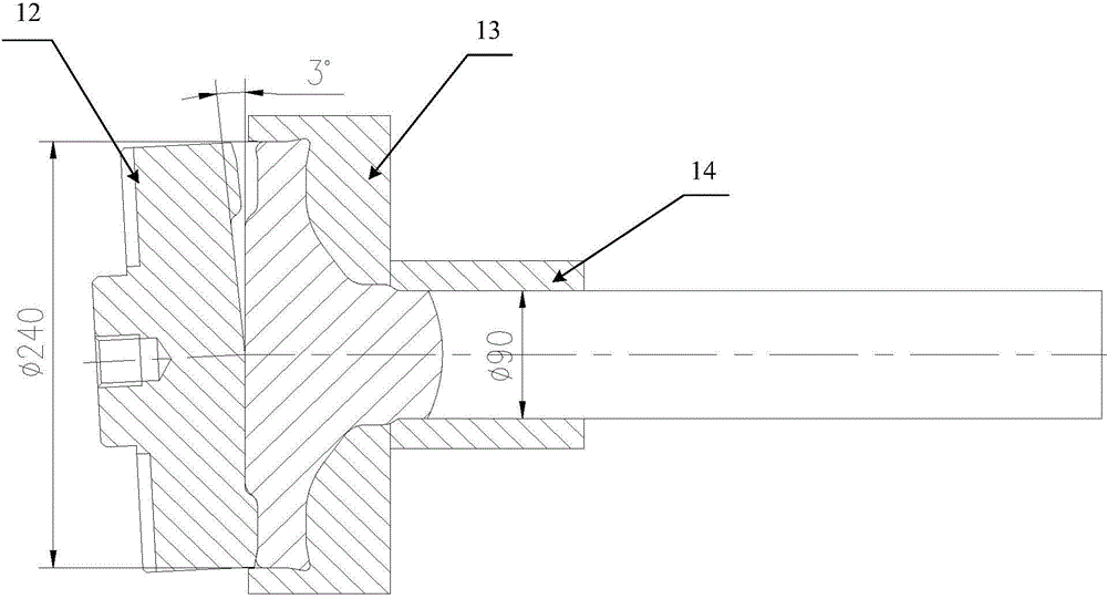
[0034] see Figure 1-Figure 10 , figure 1 It is a structural schematic diagram of the state of raw material bars in the prior art; figure 2 The state when the semi-axis is preform...


PUM

PropertyMeasurementUnit
lengthaaaaaaaaaa
diameteraaaaaaaaaa

Abstract

The invention discloses a half axle forging forming technology. According to the half axle forging forming technology, forming is achieved through oil hydraulic presses instead of an oscillating mill. A flange forming part is preformed through a 500T oil hydraulic press first, a flange is then pressed through a 1250T oil hydraulic press, the flange is pressed first (the flange cannot be fully formed at the moment), a punch is then lifted, a flange forming press ring is placed in, and the flange is pressed again (at the moment, the stress area is small and the pressure is certain, so unit pressure is increased). The flange forming press ring is adopted for another pressing (only an outer ring of the flange is formed), and a half axle (requiring pressure more than 3000 tons generally) with the flange with the diameter phi of 370 mm can be formed through pressing by a small-tonnage hydraulic press (1250 tons). The half axle forging forming technology aims to achieve the purpose that a large half axle (with the diameter phi of the flange being 370 mm) can be formed through pressing by the small-tonnage oil hydraulic press (1250T oil hydraulic press), the problem that a half axle with a large-diameter flange is hard to develop is solved, the cost of the half axle part is reduced, and thus the cost of a finished vehicle is reduced; an enterprise can find a new market, and economic benefits of the enterprise are raised.

Description

technical field [0001] The invention relates to the technical field of forging forming, in particular to a half shaft forging forming process. Background technique [0002] At present, according to the size, shape and size of the half shaft of agricultural machinery, the diameter of the flange plate is less than φ240, and the diameter of the middle rod is less than φ90. [0003] Existing pendulum mill molding process can refer to as shown in the accompanying drawings, wherein figure 1 The raw material 11 is in the state of bar stock; first, the flange part is preformed with a 200-ton hydraulic press, the function is to thicken the head of the raw material 11, reduce the forging ratio of the swing plate, figure 2 The middle is the state of the half-shaft when it is put into the pendulum mill after preforming; then it is placed on the pendulum mill for forming, and the state of the half-shaft after the pendulum plate is formed can refer to image 3 As shown, 12 is the pendu...

Claims


Application Information

Patent Timeline
Patent Type & Authority Applications(China)
IPC IPC(8): B21J5/00B21J13/02
Inventor 李长波宫晋臣张学良蔡永和宗照东陆洪刚车广义李成志孙成香钟志辉于慧玲赵朝线郑怀刚高汝风
Owner JILIN YUANFANG MACHINERY GROUP
Why Eureka
Try Eureka