Separating forceps for abdominal cavity

A technology for separating forceps and abdominal cavity, which is applied in the field of abdominal cavity separating forceps, which can solve the problems of increasing blood vessel or tissue capillary damage, affecting long-term healing and shaping effect, increasing long-term complications of surgery, etc., so as to reduce the probability of necrosis and shorten the operation Time, complexity reduction effects

Pending Publication Date: 2019-07-12
SECOND AFFILIATED HOSPITAL OF XIAN MEDICAL UNIV
View PDF0 Cites 5 Cited by
  • Summary
  • Abstract
  • Description
  • Claims
  • Application Information

AI Technical Summary

Problems solved by technology

[0002] During laparoscopic angioplasty or tissue angioplasty, separating forceps repeatedly clamp the same part of the tissue, which can easily cause ischemic necrosis of the tissue at that part, affect long-term healing and forming effects, and increase the occurrence of long-term surgical complications
[0003] After in-depth analysis, the reasons for tissue ischemic necrosis are as follows. The existing separating forceps are composed of two mutually interlocking forceps. Width direction) to set several grooves to form a wavy clamping surface. When the two clamps are closed, the two clamping surfaces bite each other, that is, the crest of one clamping surface contacts the trough of the other clamping surface; When tightening the blood vessel or tissue, the two clamps can make the blood vessel or tissue in contact with the clamping surface fully stressed, ensuring the firmness of the blood vessel or tissue clamping; but this also improves the contact between the blood vessel or tissue and the clamping force. The force-bearing area increases the damage of blood vessels or capillaries in tissues during repeated clamping, eventually causing tissue ischemia and necrosis
[0004] Secondly, after the suturing of blood vessels or tissues is completed with separating forceps, the suture thread needs to be cut. The existing method is to replace the thread cutter after the suture is completed, and extend it into the abdominal cavity to cut the suture thread. The whole operation process Complicated, prolonging surgery time

Method used


Image

  • Separating forceps for abdominal cavity
  • Separating forceps for abdominal cavity
  • Separating forceps for abdominal cavity

Examples


Embodiment Construction

[0040] The present invention will be further described in detail below in conjunction with the accompanying drawings, which are to explain rather than limit the present invention.

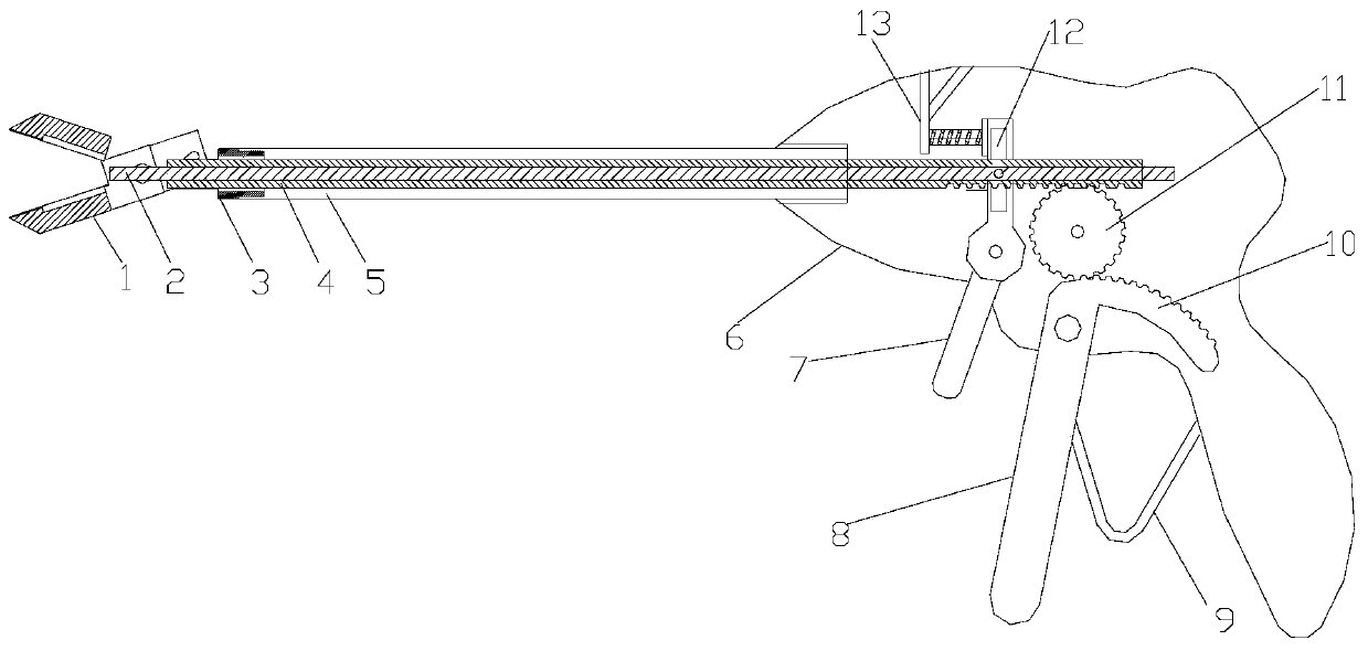
[0041] see figure 1 , a multifunctional abdominal cavity separation forceps, including a forceps body, a pull rod 4, a fixed rod 5 and a handle 6.

[0042] Among them, the clamp body is connected with one end of the fixed rod 5, the other end of the fixed rod 5 is connected with the handle 6, and the pull rod 4 is arranged in the fixed rod 5, one end of which is extended to connect with the clamp body, and the other end is extended into the handle 6 to connect with the clamp body. The pull rod control handle 8 on the handle 6 is connected, and the pull rod control handle 8 is driven to move the pull rod 4, thereby driving the clamp body to close and open.

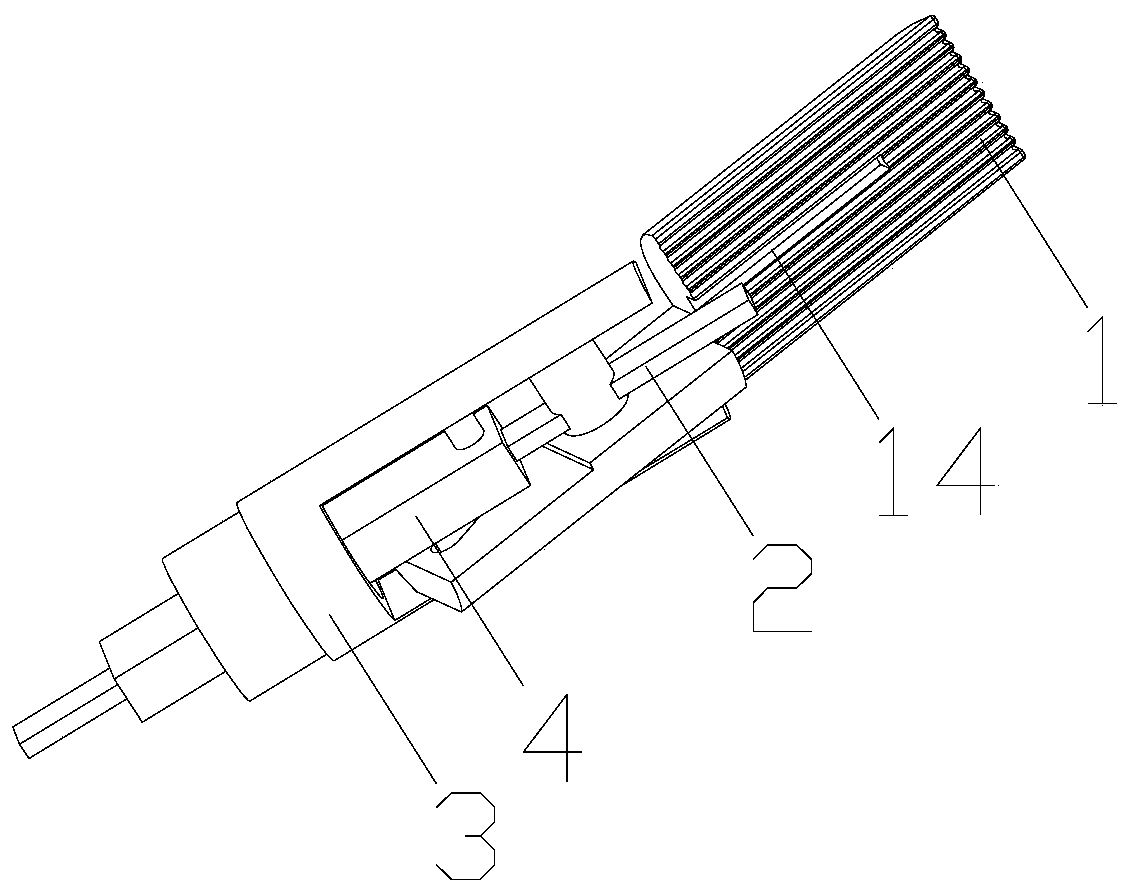
[0043] see figure 2 , the clamp body includes a support seat 3, a pull rod 4 and two opposite clamps, the two clamps 1 are hinged at one end...


PUM


Abstract

The invention discloses separating forceps for the abdominal cavity. The separating forceps comprises two opposite clamp forceps, the surfaces of the clamp forceps are provided with grooves formed inthe length direction of the clamp forceps, a pull rod control handle closes the two clamp forceps through a pull rod to clamp tissue, the tops of the grooves of the two clamp forceps apply clamping force to the tissue, the grooves do not apply clamping force, therefore, the stress area of the tissue is reduced, necrosis of capillaries in the tissue is reduced, and the necrosis probability of the clamped tissue is lowered. Meanwhile, a cutter is arranged on the separating forceps, the movement direction of the cutter is controlled through a cutter control handle, the tissue or suture between the two clamp forceps can be cut, the practicability of the separating forceps is improved, the operation complexity is lowered, and the operation time is shortened.

Description

technical field [0001] The invention relates to the technical field of medical devices, in particular to an abdominal cavity separating forceps. Background technique [0002] When performing laparoscopic vascular or tissue plastic surgery, the separation forceps repeatedly clamps the same part of the tissue, which is easy to cause tissue ischemia and necrosis in this part, which affects the long-term healing and forming effect, and increases the occurrence of long-term complications of the operation. [0003] After in-depth analysis, the causes of tissue ischemia and necrosis are as follows. The existing separation clamp consists of two clamps that are connected to each other. The closing and opening of the clamps are controlled by the handle. The width direction) is provided with several grooves to form a wave-shaped clamping surface. When the two clamps are closed, the two clamping surfaces are engaged with each other, that is, the crest of one clamping surface is in conta...

Claims


Application Information

Patent Timeline
Patent Type & Authority Applications(China)
IPC IPC(8): A61B17/295A61B17/04
CPCA61B17/0467A61B17/2909A61B17/295A61B2017/2926
Inventor 倪锋郑亮潘奇陈淋惠鹏宇杜永辉于靳胡小剑李凯旋张志刚赵志强
Owner SECOND AFFILIATED HOSPITAL OF XIAN MEDICAL UNIV
Why Eureka
Try Eureka