Cone crusher with radial shearing and crushing function
A cone crusher and functional technology, applied in grain processing and other directions, can solve the problems of no tangential shearing and crushing, loss of crushing force, etc., and achieve the effect of improving crushing efficiency
- Summary
- Abstract
- Description
- Claims
- Application Information
AI Technical Summary
Problems solved by technology
Method used
Image
Examples
Embodiment 1
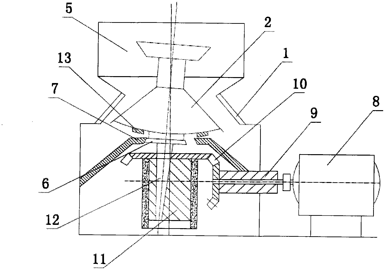
[0059] Embodiment 1: as figure 1 and image 3 As shown, a crushing wall with a radial shear crushing function includes a frame 5 on which a motor 8 is mounted, and the motor 8 is connected to a transmission shaft 9 . The transmission shaft 9 is connected with a bevel gear 10, and drives the eccentric sleeve 11 to rotate through the bevel gear 10. The main shaft 12 is freely inserted in the tapered hole of the eccentric bushing 11 . The moving cone 2 is fixed on the main shaft 12 and supported on the spherical bearing 13 . The fixed cone 1 is set on the frame 5, and the fixed cone 1 and the moving cone 2 are set to form a crushing chamber.
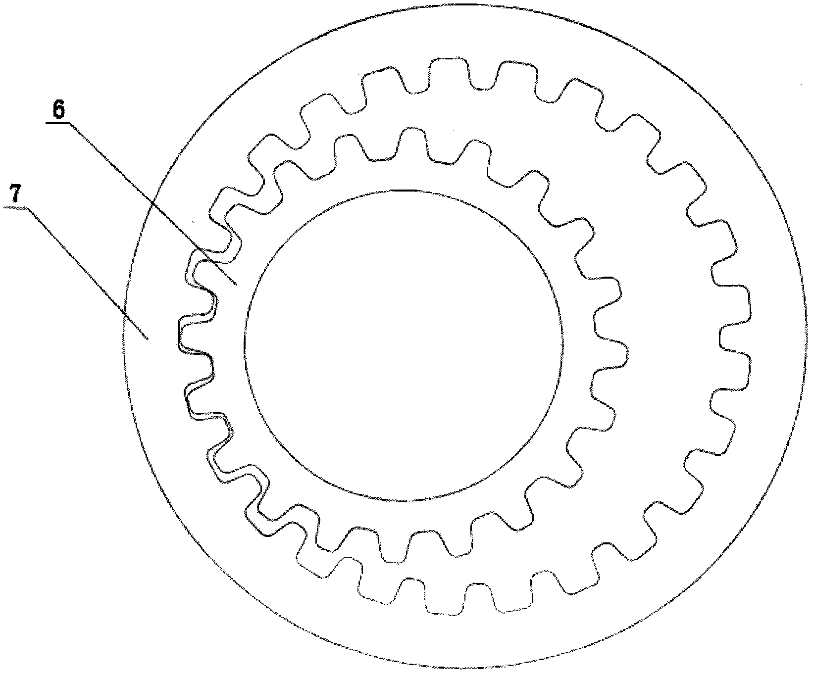
[0060] The bottom of the moving cone 2 is provided with an outer ring gear 6, and the frame 5 is provided with an inner ring gear 7, and the outer ring gear 6 and the inner ring gear 7 mesh to form a planetary gear differential mechanism to limit the free movement of the moving cone 2.
[0061] The annular centerline of the outer ring ...
Embodiment 2
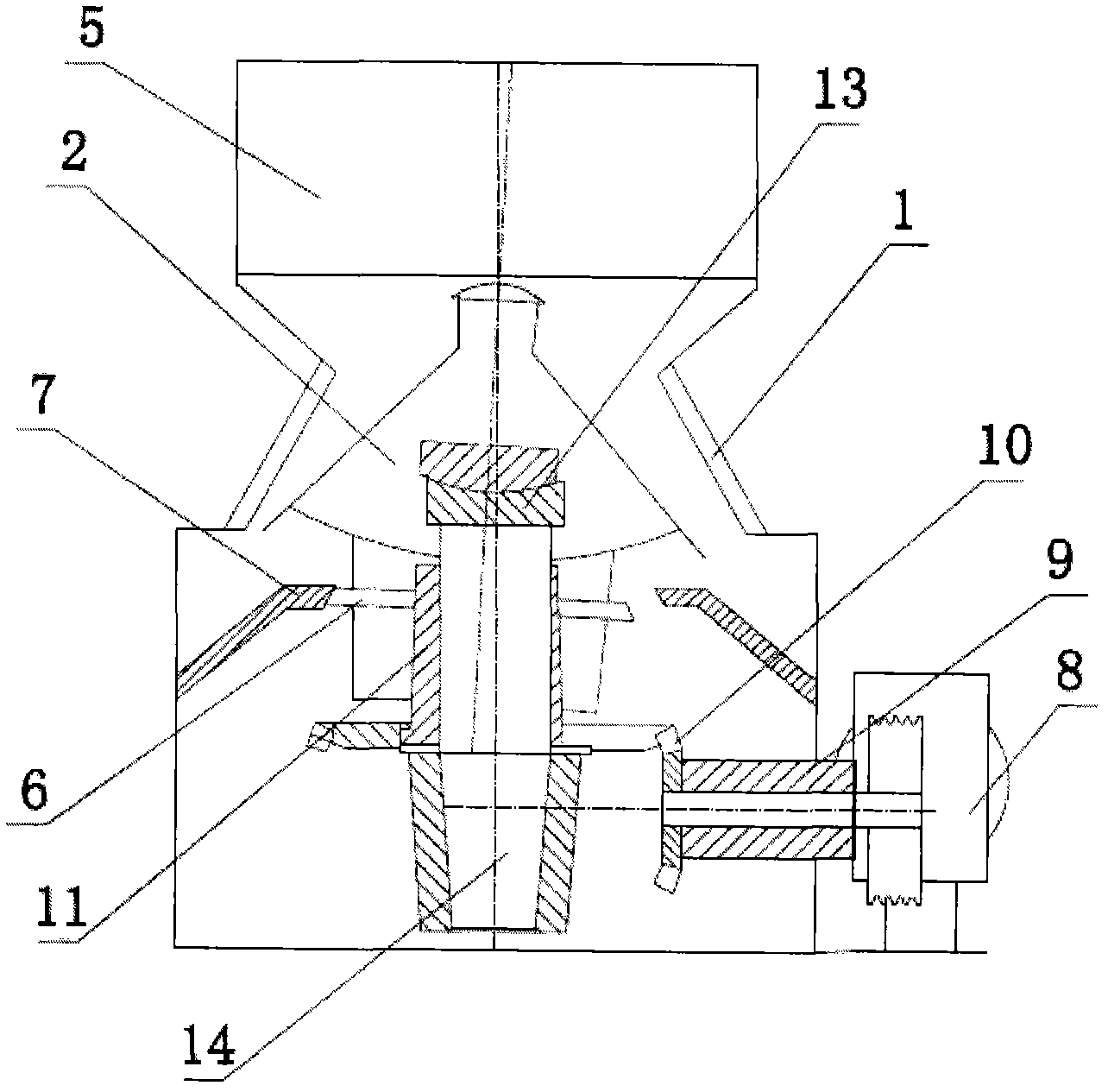
[0062] Embodiment 2: as figure 2 and image 3 As shown, a crushing wall with a radial shear crushing function includes a frame 5 on which a motor 8 is mounted, and the motor 8 is connected to a transmission shaft 9 . The transmission shaft 9 is connected with a bevel gear 10, and drives the eccentric sleeve 11 to rotate through the bevel gear 10. The vertical shaft 14 is fixed on the frame 5 , and the eccentric shaft sleeve 11 is sleeved on the vertical shaft 14 . The moving cone 2 is supported by a spherical bearing 13 and freely sleeved on the outside of the eccentric shaft sleeve 11 . The fixed cone 1 is set on the frame 5, and the fixed cone 1 and the moving cone 2 are set to form a crushing chamber.
[0063] The outer ring gear 6 is arranged on the side wall of the lower end of the moving cone 2, and the inner ring gear 7 is arranged on the frame 5, and the outer ring gear 6 and the inner ring gear 7 are meshed to form a planetary gear differential mechanism, which li...
Embodiment 3
[0065] Embodiment 3: as Figure 4 As shown, the inner side of the fixed cone 1 is fixed with a rolling mortar wall, and the outer side of the movable cone 2 is fixed with a crushing wall, and the crushing wall is sleeved in the rolling socket wall to form a crushing chamber. A spiral rib 3 is provided on the outer crushing wall of the movable cone 2 and on the inner rolling socket wall of the fixed cone 1 . The helical direction of the ribs 3 on the outer crushing wall of the movable cone 2 is opposite to the helical direction of the ribs 3 on the inner rolling wall of the fixed cone 1 . All the other are with embodiment 1.
PUM
 Abstract
Description
Claims
Application Information
 - R&D
- Intellectual Property
- Life Sciences
- Materials
- Tech Scout
- Unparalleled Data Quality
- Higher Quality Content
- 60% Fewer Hallucinations
Browse by: Latest US Patents, China's latest patents, Technical Efficacy Thesaurus, Application Domain, Technology Topic, Popular Technical Reports.
© 2025 PatSnap. All rights reserved.Legal|Privacy policy|Modern Slavery Act Transparency Statement|Sitemap|About US| Contact US: help@patsnap.com


