Plunger pump fluid end assembly

A liquid end, plunger pump technology, applied in pump components, variable capacity pump components, liquid fuel engines, etc., can solve problems such as high cost, reduced pump comprehensive life, and inability to operate normally, reducing the force area. , Improve the overall efficiency, the effect of reducing the ineffective volume

Inactive Publication Date: 2013-10-30
NINGBO HELI MECHANICAL PUMP CO LTD
View PDF6 Cites 6 Cited by
  • Summary
  • Abstract
  • Description
  • Claims
  • Application Information

AI Technical Summary

Problems solved by technology

The overall service life of the pump is reduced, and it cannot operate normally. Under the national policy of energy saving and emission reduction, there is no other way out for the sewage discharge in the oil field, and it can only be injected into the ground in time for oil displacement.
However, due to the heavy workload and high cost of sewage treatment, and the construction of sewage treatment stations in oil fields often cannot keep up with the actual needs, the sewage reinjection discharged from the produced crude oil is only completed by high-pressure water injection pumps

Method used


Image

  • Plunger pump fluid end assembly
  • Plunger pump fluid end assembly
  • Plunger pump fluid end assembly

Examples


Embodiment 1

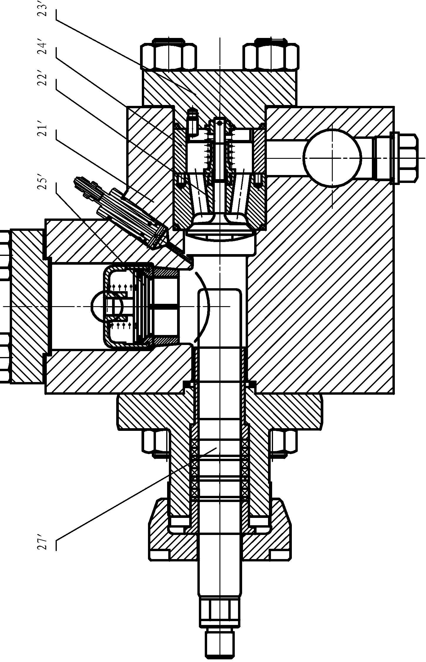
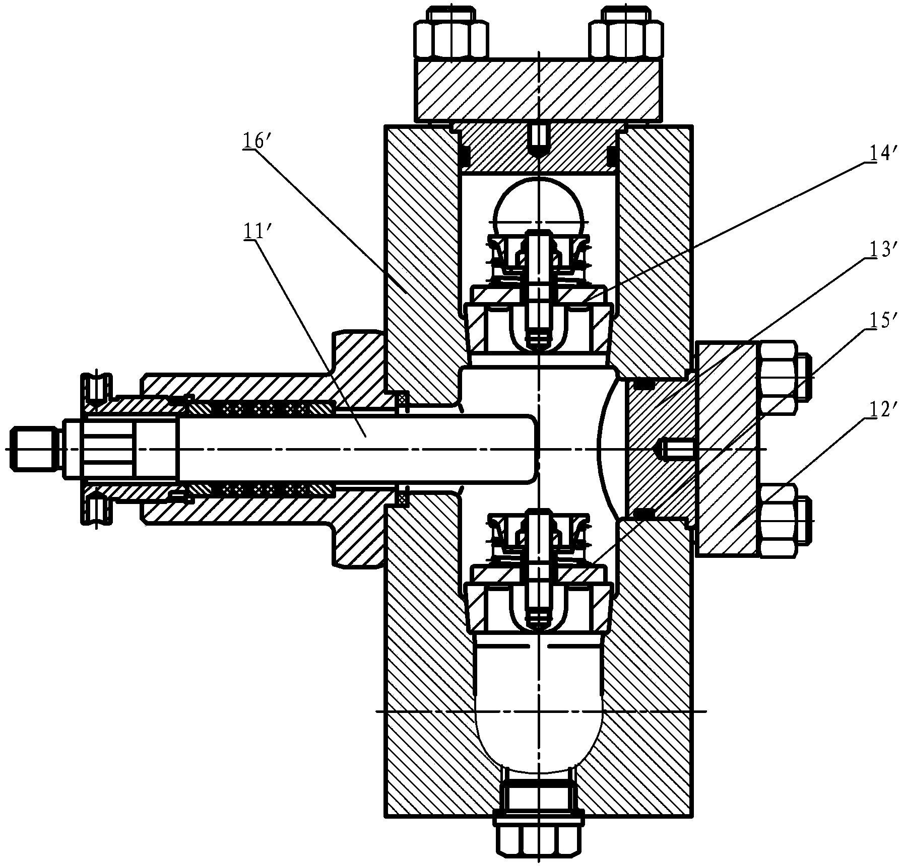
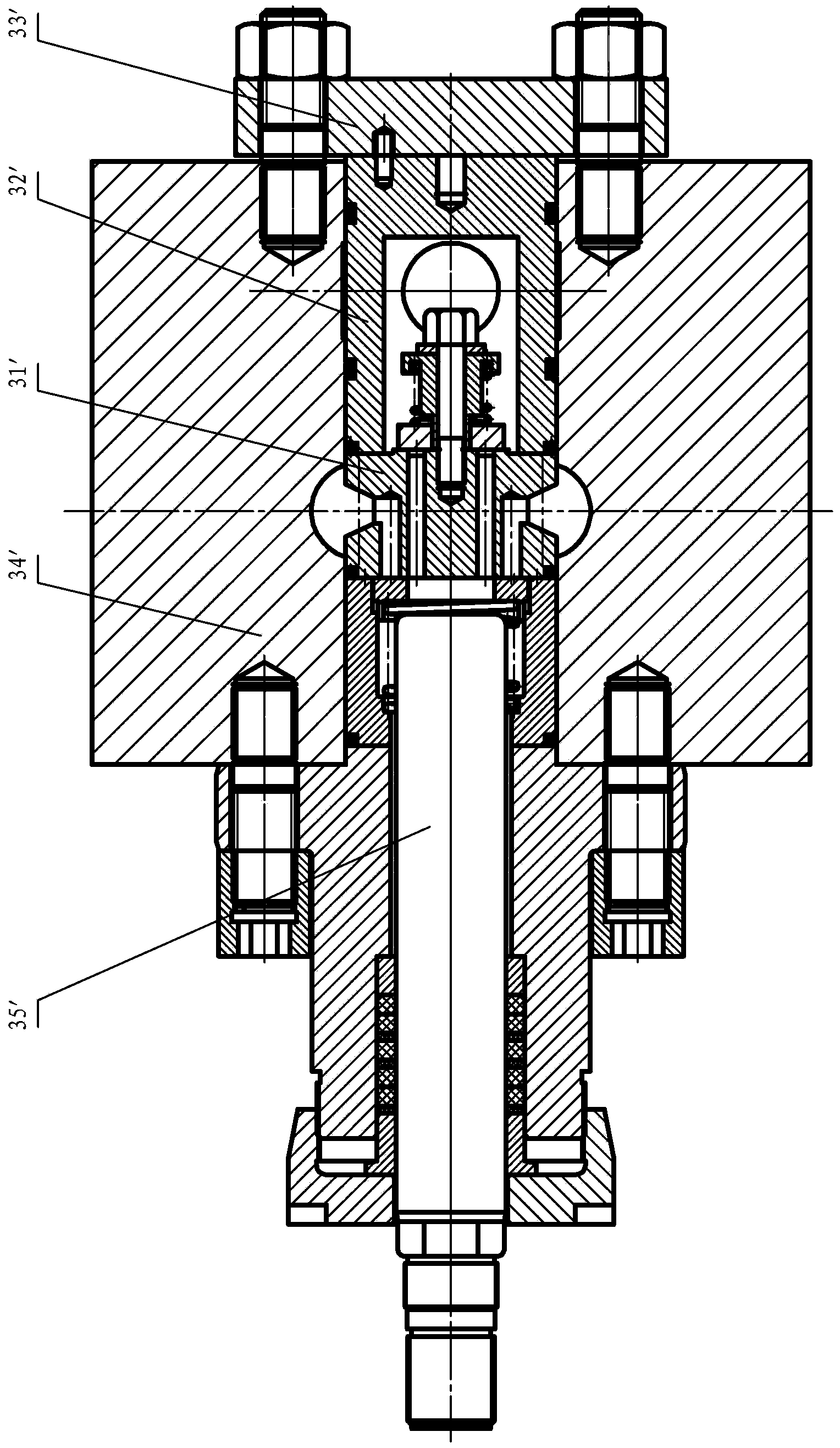
[0028] Such as Figure 4~6 The hydraulic end assembly of the plunger pump shown includes pump body 1, seal 2, combined valve 3, liquid inlet valve 31, liquid discharge valve 32, plunger 6, upper flange 7, mesh plate 8, valve sleeve 9. Front flange 10, plug head 11, front guide sleeve 12, rear pressure ring 13, packing 14, adjusting nut 15, the pump body 1 is provided with a plunger channel 18, and the plunger 6 is movable in the plunger channel 18 Inside, the pump body 1 is provided with a vertical combination valve channel 19 which communicates with the plunger channel 18. The combination valve 3 is arranged in the valve passage, and the structure of the combination valve 3 can adopt the structure disclosed in the Chinese invention patent No. 200510050387.2. The valve 32 is arranged on the upper part, and the pump body 1 is provided with a liquid inlet chamber 16 communicating with the liquid inlet valve 31 of the combined valve 3 , and the pump body 1 is provided with a liq...

Embodiment 2

[0037] The difference from Embodiment 1 is that the liquid inlet chamber 16 is arranged in front of the pump body and communicates with the liquid inlet chamber of the liquid inlet valve 31 . In this case, an additional liquid inlet manifold is required. see Figure 7 shown.

Embodiment 3

[0039] The difference from the second embodiment is that the liquid discharge chamber 17 is arranged on the upper part of the pump body and communicates with the liquid discharge chamber of the liquid discharge valve 32 , at this time, a liquid discharge manifold needs to be additionally provided. see Figure 8 shown.


PUM


Abstract

The invention relates to a plunger pump fluid end assembly which comprises a pump body (1) and a plunger (6). A plunger passage (18) is disposed inside the pump body (1), and the plunger (6) is movably arranged in the plunger passage (18). The plunger pump fluid end assembly is characterized in that a combination valve passage (19) which is arranged vertically and communicated with the plunger passage (18) is arranged in the pump body (1), a combination valve (3) is arranged in the combination valve passage, a fluid inlet valve (31) of the combination valve (3) is arranged on the lower portion while a fluid drain valve (32) of the combination valve (3) is arranged on the upper portion, and a fluid inlet cavity (16) communicated with the fluid inlet valve (31) of the combination valve (3) and a fluid drain cavity (17) communicated with the fluid drain valve (32) of the combination valve (3) are arranged on the pump body (1). The pump body of the plunger pump fluid end assembly cannot be cracked on the condition of high-pressure alternating stress, and the plunger pump fluid end assembly can work normally with media containing sand, suspended matters and the like.

Description

technical field [0001] The invention relates to a hydraulic end assembly of a plunger pump. Background technique [0002] The liquid end of the traditional plunger pump usually has the following structure: 1. Straight-through type (upper and lower valves), see attached figure 1 ;2. Three-way type (inlet valve vertical type, liquid discharge valve horizontal type), see attached figure 2 ; 3. Horizontal type (horizontal combined valve), see attached image 3 . The reliability of the liquid end, the cracking of the pump body, and the short life of the valve group of wearing parts are common problems in the liquid end of the three different shapes and structures under the condition of conveying high-pressure liquid. The analysis is as follows: [0003] The straight-through liquid end is a four-way structure, see the attached figure 1 When disassembling the plunger 11', the front flange 12' and the pressing block 13' can be disassembled from the front, which is more convenie...

Claims


Application Information

Patent Timeline
Patent Type & Authority Applications(China)
IPC IPC(8): F04B53/12
Inventor 陈明海
Owner NINGBO HELI MECHANICAL PUMP CO LTD
Why Eureka
Try Eureka