Concrete beam column pouring formwork frame and mounting method thereof

A technology of concrete and beams and columns, which is applied in the direction of construction, building structure, formwork/formwork components, etc., can solve the problems of not being too thick, low strength, waste of wood, etc., to reduce installation steps, increase service life, and facilitate installation Effect

Active Publication Date: 2019-08-09
CHINA METALLURGICAL CONSTR ENG GRP
View PDF5 Cites 2 Cited by
  • Summary
  • Abstract
  • Description
  • Claims
  • Application Information

AI Technical Summary

Problems solved by technology

The multiple vertical concave cavities provided on the template in the mold frame provide favorable conditions for its bending, but in order to ensure the strength of the entire template body and avoid the template from being partially broken by the vertical groove during the bending process, It requires the cooperation of many people when bending, and the bending is more difficult, and the shaping is more difficult. It can only meet the use of circular column or pile head formwork. If it is applied to rectangular or other heterogeneous formwork, there will be breakage or shaping difficult que

Method used


Image

  • Concrete beam column pouring formwork frame and mounting method thereof
  • Concrete beam column pouring formwork frame and mounting method thereof
  • Concrete beam column pouring formwork frame and mounting method thereof

Examples


Embodiment

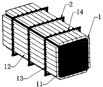
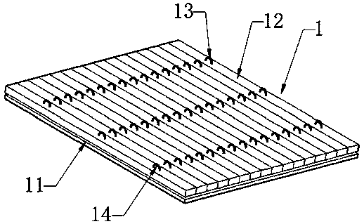
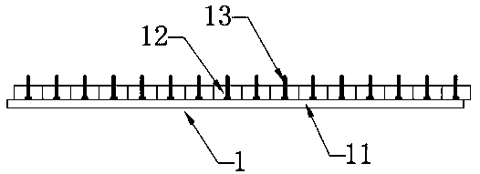
[0026] As shown in the figure, the concrete beam and column pouring formwork provided in this embodiment includes a formwork matching the shape of the beam and column, and the formwork is formed by bending two composite formworks 1 into a U shape and splicing together. The composite formwork 1 is composed of a flexible bottom layer 11 and a reinforcement layer fixedly installed on the back of the flexible bottom layer 11, the flexible bottom layer 11 is rectangular, and the reinforcement layer is composed of a plurality of rigid rectangular strips 12 vertically arranged along the width direction of the flexible bottom layer 11 The side ends of adjacent rigid rectangular strips 12 are attached to each other; a plurality of U-shaped buckles 13 are installed at intervals on the outer end surface of each composite template 1 reinforcement layer, and the opening side of the U-shaped buckles 13 is fixed on the hard In the rectangular bar 12, and arranged in multiple rows, an arc chan...


PUM

PropertyMeasurementUnit
Thicknessaaaaaaaaaa
Thicknessaaaaaaaaaa
Thicknessaaaaaaaaaa

Abstract

The present invention discloses a concrete beam column pouring formwork frame and a mounting method thereof. The concrete beam column pouring formwork frame is formed in the mode that a flexible composite formwork is bent to be a circle or polygon or rectangle and then is defined or in the mode that two or more composite formworks are bent to be the arc shape or the U shape or the L shape or the polygon and then are spliced; each composite formwork is formed by a flexible bottom layer and a reinforcing layer fixedly mounted on the back face of the flexible bottom layer, and each reinforcing layer is composed of a plurality of hard rectangular strips, wherein the side ends of the hard rectangular strips are attached; and a plurality of U-shaped buckles are mounted on the outer end faces ofthe multiple hard rectangular strips at intervals, the open sides of the U-shaped buckles are fixedly mounted in the hard rectangular strips, the U-shaped buckles are arrayed in multiple rows, an arc-shaped channel is formed between each row of U-shaped buckle and the corresponding reinforcing layer, and a shaping part with the length being greater than each arc-shaped channel is inserted in eacharc-shaped channel located in the same plane in a penetrating mode. According to the concrete beam column pouring formwork frame and the mounting method thereof, the service life is long, the mountingstrength is high, manufacturing and construction are convenient, and the mounting demands of various special-shaped formworks can be met.

Description

technical field [0001] The invention relates to a formwork, in particular to a concrete beam and column pouring formwork frame and an installation method thereof. Background technique [0002] At present, when pouring pile heads, beam columns or shear walls, it is necessary to combine a layer of wooden formwork on the periphery of the reinforcement cage to form a formwork, and after pouring concrete into the formwork to form beams and columns, the wooden formwork is removed. Generally speaking, the wooden formwork of the formwork requires the construction personnel to cut the plank on site according to the size of the pile head, beam column or shear wall, and reinforce the formwork with a layer of wooden beams and steel bars outside the formwork. The setting method of the above-mentioned mold frame is labor-intensive and time-consuming, and can only meet the use of a template with one specification, so the versatility is poor, and the waste of wood in the production process ...

Claims


Application Information

Patent Timeline
IPC IPC(8): E04G9/08E04G17/00
CPCE04G9/083E04G17/001
Inventor 杨洋邱长林冯翔
Owner CHINA METALLURGICAL CONSTR ENG GRP
Why Eureka
Try Eureka