Silicone pad transferring and fitting device

A technology of laminating equipment and silicone pads, applied in the directions of material gluing, mechanical equipment, connecting components, etc., can solve the problems of low efficiency of silicone pads, uneven pressing, poor positioning effect, etc., to achieve good fixing effect and work. High efficiency and the effect of improving work efficiency

Active Publication Date: 2019-08-09
GUANGDONG XG INTELLIGENT SYST CO LTD
8 Cites 1 Cited by

AI-Extracted Technical Summary

Problems solved by technology

[0005] Aiming at the deficiencies of the prior art, the present invention provides a silicone pad turnover bonding equipment, which has the advantages of accurate positioning, goo...

Abstract

The invention relates to the technical field of silicone pad production, in particular to a silicone pad transferring and fitting device which comprises a rotary table device, a manipulator and a loading fixture device. The loading fixture device is fixedly connected to the bottom part of the manipulator; the rotary table device is located right under the loading fixture device, and comprises a rack; a rotary table fixing device is fixedly connected to the middle of the rack; a rotary table rotating device is fixedly connected to the bottom part of the rotary table fixing device; an air cylinder drive device is fixedly connected to the middle of the rack; and the rotary table fixing device comprises a fixed plate. The silicone pad transferring and fitting device provided by the invention is accurate in positioning, good in fixing effect and high in working efficiency, a glue on the top part of a silicone pad can be uniformly applied during the fitting of the product and the silicone pad, meanwhile, air between the product and the silicone pad can be discharged, and the tightness in fitting between the product and the silicone pad is ensured, so that the occurrence of the phenomenaof hollowing and edge warping is prevented.

Application Domain

Technology Topic

Image

  • Silicone pad transferring and fitting device
  • Silicone pad transferring and fitting device
  • Silicone pad transferring and fitting device

Examples

  • Experimental program(1)

Example Embodiment

[0049] The technical solutions in the embodiments of the present invention will be clearly and completely described below in conjunction with the accompanying drawings in the embodiments of the present invention. Obviously, the described embodiments are only a part of the embodiments of the present invention, rather than all the embodiments. Based on the embodiments of the present invention, all other embodiments obtained by those of ordinary skill in the art without creative work shall fall within the protection scope of the present invention.
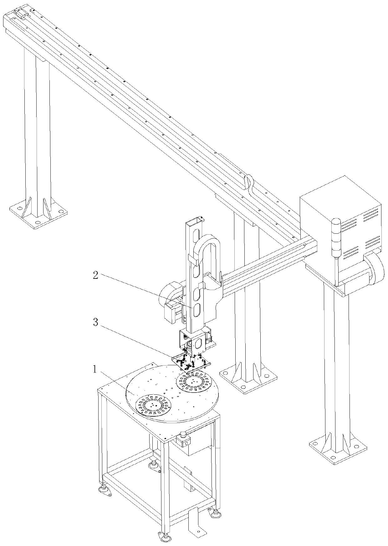
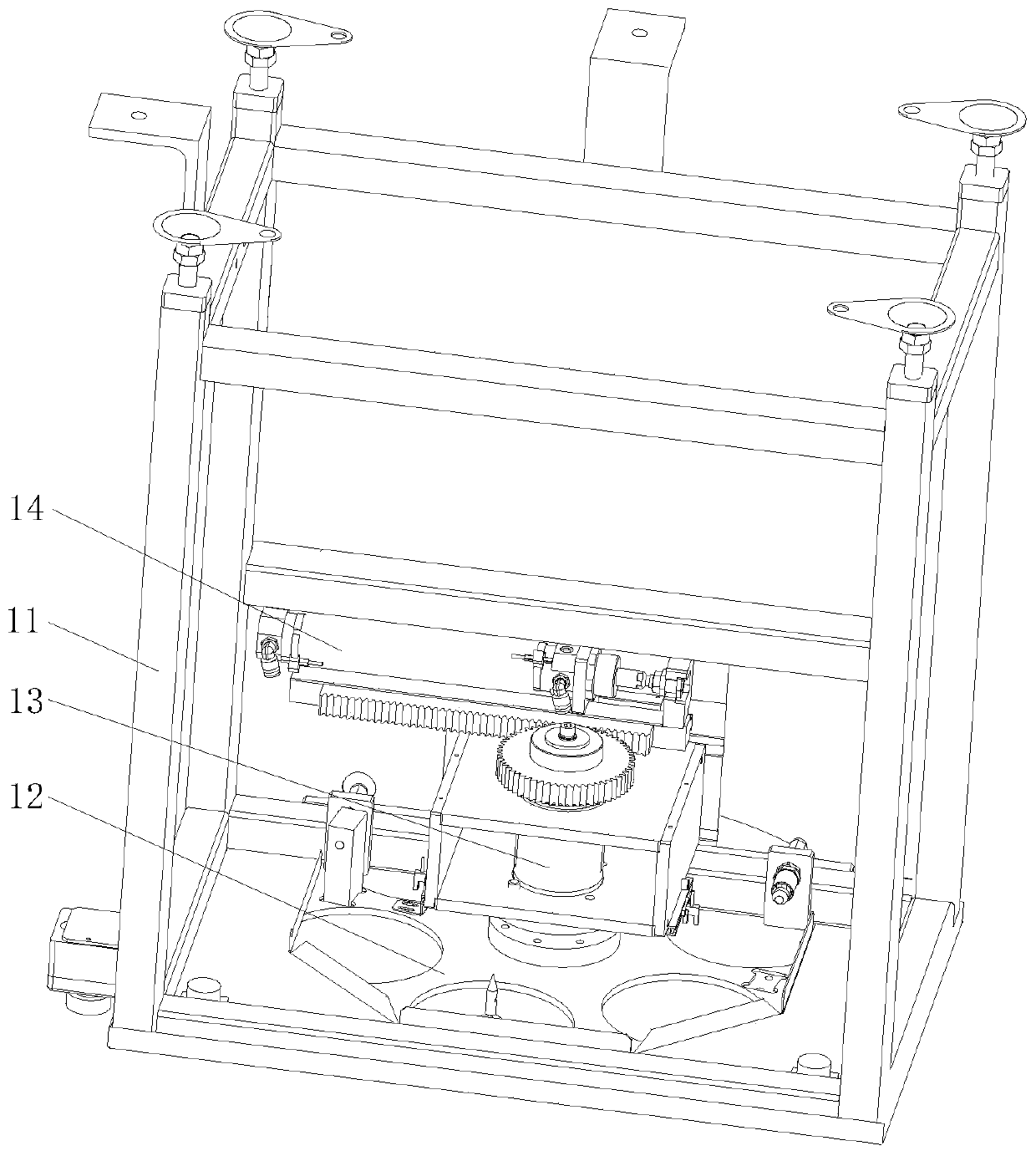
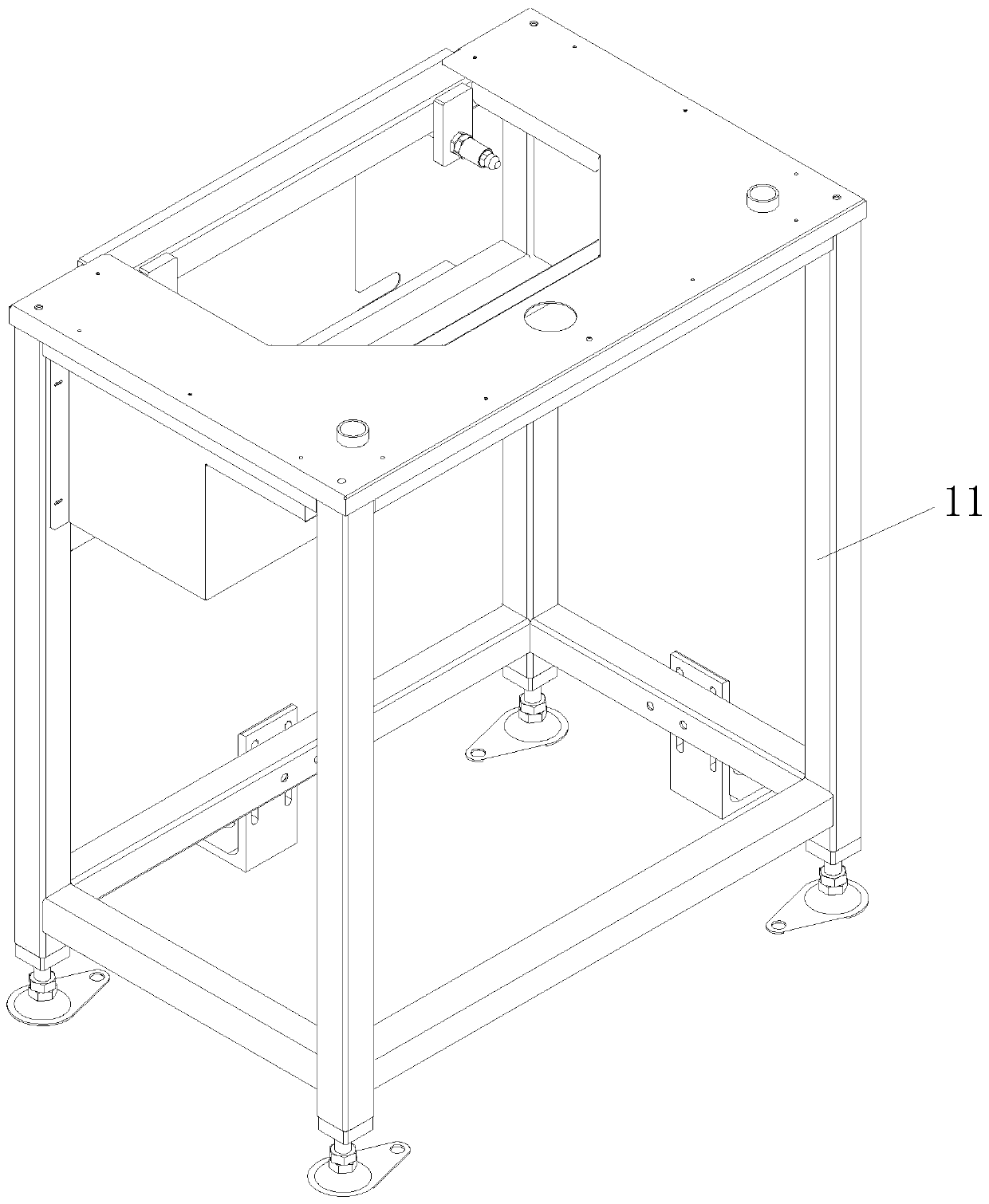
[0050] See Figure 1-21 , A silicone pad turnover laminating equipment, comprising a turntable device 1, a manipulator 2 and a loading fixture device 3. The loading fixture device 3 is fixedly connected to the bottom of the manipulator 2, and the turntable device 1 is located directly below the loading fixture device 3. Through the use of the turntable device 1 and the loading fixture device 3, the silicone sheet is placed on the rubber pad carrier 126 on the turntable device 1 with the adhesive side up, and the suction cup assembly 33 on the loading fixture device 3 absorbs the product , The manipulator drives the feeding fixture device 3 to move downwards, and pushes the product downward to make it fit with the silicone paste, thereby completing the silicone sheet pasting industry, improving work efficiency and ensuring the accuracy of positioning.
[0051] The turntable device 1 includes a frame 11, a turntable fixing device 12 is fixedly connected to the middle of the frame 11, a turntable rotating device 13 is fixedly connected to the bottom of the turntable fixing device 12, and a cylinder driving device 14 is fixedly connected to the middle of the frame 11.
[0052] The rack 11 includes a rack frame 111. The four corners at the bottom of the rack frame 111 are movably connected with fixed foot cups 112. Both sides of the bottom of the rack frame 111 are fixedly connected with foot plates 113. The top of the rack frame 111 is fixedly connected with The table top sheet metal 114, the inside of the frame frame 111 is fixedly connected with a protective cover 115, and the protective cover 115 is located at the bottom of the table top sheet metal 114, the top of the back of the frame frame 111 is fixedly connected with a cover plate 116, and the cover plate 116 is located in the protective cover On the left side of the back of the cover 115, the top of the table top sheet metal 114 is fixedly connected with flat buttons 117, both ends of the inner top of the frame frame 111 are fixedly connected to the oil pressure buffer 119, the outer surface of the oil pressure buffer 119 A positioning stop nut 118 is sleeved.
[0053] The turntable fixing device 12 includes a fixing plate 121, which is fixedly connected to the top of the frame 11, the turntable rotating device 13 is inserted into the middle of the fixing plate 121, and the middle of the right side of the frame 11 is fixedly connected with an emergency stop switch assembly 123, the left and right sides inside the fixed plate 121 are respectively fixedly connected with the pressure regulating valve assembly 124 and the solenoid valve assembly 125, the top of the turntable rotating device 13 is fixedly connected with a rotating platen 122, and both sides of the top of the rotating platen 122 are fixedly connected with Rubber pad carrier 126.
[0054] The emergency stop switch assembly 123 includes an emergency stop button box 1232. The top of the emergency stop button box 1232 is movably connected with an emergency stop switch button 1231, and the bottom of the emergency stop button box 1232 is fixedly connected with a switch box mounting plate 1233 and a switch box mounting plate 1233. It is fixedly connected to the middle of the right side of the rack 11.
[0055] The pressure regulating valve assembly 124 includes a pressure regulating valve body 1241. One side of the pressure regulating valve body 1241 is fixedly connected with a hand slide valve 1242, and the other side of the pressure regulating valve body 1241 is fixedly connected with a pressure regulating pipe joint 1243.
[0056] The solenoid valve assembly 125 includes a first solenoid valve 1251. The top of the first solenoid valve 1251 is fixedly connected with a speed control valve 1252, and both sides of the bottom of the first solenoid valve 1251 are fixedly connected with a first silencer 1253 and a first solenoid valve 1251. An electromagnetic pipe joint 1254 is fixedly connected to the middle of the bottom.
[0057] The turntable rotating device 13 includes a first seated bearing 131, the first seated bearing 131 is inserted into the middle of the fixed plate 121, the middle of the first seated bearing 131 is inserted into the first main shaft 132, and the rotary table 122 is fixedly connected On the top of the first main shaft 132, the bottom of the outer surface of the first main shaft 132 is sleeved with a collar 133, the outer surface of the collar 133 is sleeved with a gear 134, and the bottom of the rotary table 122 is fixedly connected with the limit block 135 and the sensor. 片136.
[0058] The cylinder driving device 14 includes a bottom plate 141, which is fixedly connected to the left side of the middle of the frame 11, a cylinder mounting block 145 is fixedly connected to the left middle part of the bottom plate 141, and two grooves are fixedly connected to the left middle part of the bottom plate 141. The sliding block 1412 and the cylinder mounting block 145 are located above the two sliding blocks 1412. The two sliding blocks 1412 are slidably connected with a sliding rail 1411. Through the cooperation of the sliding rail 1411 and the sliding block 1412, the cylinder 1410 is operated and driven When the rack 1413 moves left and right, since the left side of the slide rail 1411 is fixedly connected to the rack mounting block 146, and the slide rail 1411 is slidably connected to the inside of the two sliders 1412, the two sliders 1412 are mounted on the bottom plate 141, The slide rail 1411 is continuously moved left and right inside the two sliding blocks 1412, thereby ensuring the stability of the rack 1413 when moving left and right, and further ensuring the stability of the rotating table 122 when rotating, and the left side of the slide rail 1411 is fixed A rack mounting block 146 is connected. The cylinder mounting block 145 is sleeved with a cylinder 1410, and the cylinder 1410 is located on the top of the rack mounting block 146. A rack 1413 is fixedly connected to the left side of the rack mounting block 146. The rack is mounted One side of the top of the block 146 is fixedly connected with a cylinder push block 147, and the cylinder push block 147 and the output end of the cylinder 1410 are on the same horizontal line. Two cylinder pipe joints 1414 are inserted on both sides of the outer surface of the cylinder 1410, and the input of the cylinder 1410 The end is sleeved with a floating joint 1415, the left side of the bottom plate 141 is fixedly connected with a reinforcing plate 144, the reinforcing plate 144 is located under the rack 1413, both sides of the reinforcing plate 144 are fixedly connected with a supporting plate 143, one of the two supporting plates 143 A bearing seat plate 142 is fixedly connected to the bottom of the shaft, and the bottom of the first main shaft 132 passes through the middle of the bearing seat plate 142 and the reinforcing plate 144 and extends to the bottom of the reinforcing plate 144. The gear 134 and the rack at the bottom of the first main shaft 132 1413 is movably connected. The bottoms of the two support plates 143 are fixedly connected with an optical fiber mounting seat 148, and the sides of the two optical fiber mounting seats 148 are fixedly connected with a first slot-type photoelectric switch 149, which is driven by the turntable rotating device 13 and the cylinder driving device 14. In conjunction with use, the cylinder 1410 is continuously contracted and extended during operation. The cylinder push block 147 and the rack mounting block 146 can drive the rack 1413 to continuously move left and right. The rack 1413 meshes with the gear 134 and is driven by the first spindle 132 to rotate When the platen 122 rotates, the silicone sheet on the rubber pad carrier 126 can be moved to just below the loading fixture device 3. At the same time, the silicone pad can be placed on the top of the rotating platen 122 when the silicone pad is attached. On the top of the rubber pad carrier 126, the division of labor and collaboration are performed at the same time, which further improves the work efficiency of the silicone sheet pasting industry.
[0059] The loading fixture device 3 includes a mounting base 31. The right side of the top of the mounting base 31 is inserted with a spindle assembly 32. The bottom of the spindle assembly 32 passes through the mounting base 31 and extends to the bottom of the mounting base 31. The bottom of the spindle assembly 32 is fixed. The suction cup assembly 33 is connected, the top of the mounting base plate 31 is fixedly connected with a fixture fixing sheet metal 36, the inner top wall of the fixture fixing sheet metal 36 is fixedly connected with a vacuum connection assembly 34, and the bottom of the vacuum connection assembly 34 is fixedly connected with a vacuum system assembly 35 , The left side of the top of the mounting base plate 31 is fixedly connected with a stepping motor 311, the output shaft of the stepping motor 311 is fixedly connected with a first synchronization wheel 37 through a coupling, and the first synchronization wheel 37 is driven with the main shaft assembly 32 through a timing belt 38 The right side of the mounting base plate 31 is fixedly connected with a sensor mounting plate 39, the top of the sensor mounting plate 39 is fixedly connected with a second slot-type photoelectric switch 312, and the middle of the top of the mounting base plate 31 is fixedly connected with a tension block 310, the tension block The top of 310 is movably connected with a roller 313, and the roller 313 is in contact with the inner middle part of the timing belt 37. Through the setting of the feeding clamp device 3, the suction force generated by the suction cup assembly 33 when working can adsorb the product, and the stepping motor 311 works The operation drives the first synchronous wheel 37 to rotate, the second synchronous wheel 323 rotates through the synchronous belt 38, and the suction cup assembly 33 rotates through the second main shaft 322, so that the product rotates synchronously. When the product is attached to the silicone pad, the The glue on the top of the silicone pad is spread more evenly, and the air between the product and the silicone pad can be discharged, which ensures the tightness of the product and the silicone pad, thereby preventing the occurrence of hollowing and warping of the silicone pad.
[0060] The spindle assembly 32 includes a second seated bearing 321. The second seated bearing 321 is inserted on the right side of the top of the mounting base plate 31. The second seated bearing 321 is inserted into the second spindle 322, and the suction cup assembly 33 is fixedly connected. At the bottom of the second main shaft 322, the top of the second main shaft 322 is sleeved with a second synchronous wheel 323, and the synchronous belt 38 is sleeved on the second synchronous wheel 323, and the top of the second belt bearing 321 is fixedly connected with an induction sheet 324.
[0061] The suction cup assembly 33 includes a suction cup mounting plate 331, the bottom of the suction cup mounting plate 331 is fixedly connected with a vacuum suction cup 332, the top of the suction cup mounting plate 331 is fixedly connected with a suction cup tube joint 333, and the bottom of the suction cup tube joint 333 and the top of the vacuum suction cup 332 Connected.
[0062] The vacuum connection assembly 34 includes a vacuum connection plate 341, both sides of the vacuum connection plate 341 are fixedly connected with a vacuum pipe joint 342, and both sides of the bottom of the vacuum connection plate 341 are fixedly connected with a rotary joint 343.
[0063] The vacuum system assembly 35 includes a vacuum bottom plate 351, the top left end of the vacuum bottom plate 351 is fixedly connected to a fluid control valve 352, and the other end of the top left side of the vacuum bottom plate 351 is fixedly connected to a second solenoid valve 353. A vacuum gauge 354 is fixedly connected to the left side through a bracket 355, and the vacuum gauge 354 is connected to the second solenoid valve 353. The middle of the top right side of the vacuum bottom plate 351 is fixedly connected to a second speed regulating valve 356, and the right side of the fluid control valve 352 A vacuum generator 357 is connected, and a second muffler 358 is inserted on the right side of the vacuum generator 357. A vacuum connector 359 is fixedly connected to the fluid control valve 352, the second solenoid valve 353 and the second speed regulating valve 356.
[0064] Working principle: Place the silicone sheet on the rubber pad carrier 126 on the turntable device 1 with the adhesive side up. The cylinder 1410 is continuously contracted and extended in operation. The rack can be driven by the cylinder push block 147 and the rack mounting block 146 1413 continuously moves left and right. The rack 1413 meshes with the gear 134. The first spindle 132 drives the rotating platen 122 to rotate, and the silicone sheet on the rubber pad carrier 126 can be moved to just below the loading fixture device 3, and the material is loaded. The suction force generated by the suction cup assembly 33 on the clamp device 3 when it is working can adsorb the product, and the manipulator drives the feeding clamp device 3 to move downwards, pushing the product downward to make it fit with the silicone rubber, and the stepping motor 311 works The first synchronous wheel 37 is driven to rotate, the second synchronous wheel 323 is rotated through the synchronous belt 38, and the suction cup assembly 33 can be driven to rotate through the second main shaft 322, so that the product rotates synchronously. When the product is attached to the silicone pad, the silicone The glue on the top of the pad is spread more evenly, and at the same time, the air between the product and the silicone pad can be exhausted, which ensures the tightness of the product and the silicone pad. When the silicone pad is attached, the silicone pad can be placed on The top of another rubber pad carrier 126 on the top of the rotating platen 122 is divided into labor and collaboration for simultaneous operations.
[0065] It should be noted that in this article, relational terms such as first and second are only used to distinguish one entity or operation from another entity or operation, and do not necessarily require or imply one of these entities or operations. There is any such actual relationship or order between. Moreover, the terms "include", "include" or any other variants thereof are intended to cover non-exclusive inclusion, so that a process, method, article or device including a series of elements not only includes those elements, but also includes those that are not explicitly listed Other elements of, or also include elements inherent to this process, method, article or equipment.
[0066] Although the embodiments of the present invention have been shown and described, those of ordinary skill in the art can understand that various changes, modifications, and substitutions can be made to these embodiments without departing from the principle and spirit of the present invention. And variations, the scope of the present invention is defined by the appended claims and their equivalents.

PUM

no PUM

Description & Claims & Application Information

We can also present the details of the Description, Claims and Application information to help users get a comprehensive understanding of the technical details of the patent, such as background art, summary of invention, brief description of drawings, description of embodiments, and other original content. On the other hand, users can also determine the specific scope of protection of the technology through the list of claims; as well as understand the changes in the life cycle of the technology with the presentation of the patent timeline. Login to view more.

Similar technology patents

Targeted advertising by context of media content

InactiveUS20110179445A1Precise positioningWeight increaseElectronic editing digitised analogue information signalsUsing detectable carrier informationTargeted advertisingMedia content
Owner:TELEFON AB LM ERICSSON (PUBL)

Speed limit sensing and vehicle speed control device

InactiveCN101554836APrecise positioningClear road informationVehicle fittingsLinear/angular speed measurementThrottle controlSpeed limit
Owner:ZHEJIANG UNIV

Network communication recorder and network communication record analysis system

ActiveCN102142720ADoes not affect normal operationPrecise positioningCircuit arrangementsInformation technology support systemData transmissionLossless compression
Owner:珠海市鸿瑞信息技术股份有限公司

Classification and recommendation of technical efficacy words

  • Good fixed effect
  • Precise positioning

Heat dissipation shockproof device of filter for high-voltage harmonic treatment

ActiveCN106195107AGood load-bearing capacityGood fixed effectNon-rotating vibration suppressionModifications using liquid coolingPistonIce storage
Owner:张晶星

Auxiliary supporting frame for ophthalmology department doctor operation

ActiveCN108938301AGood fixed effectAvoid affecting the results of surgeryOperating tablesEngineeringOphthalmology department
Owner:THE THIRD AFFILIATED HOSPITAL OF XINXIANG MEDICAL UNIV

Method and device for accurately positioning a patient in radiotherapy and/or radiosurgery

InactiveUS6865253B2Precise positioningGood flexibilityForeign body detectionRadiation beam directing meansX ray imageSoft x ray
Owner:BRAINLAB

Heart Valve Stent

InactiveUS20120283824A1Precise positioningSecure fixationSuture equipmentsStentsHeart chamberHeart valve stenosis
Owner:LUTTER GEORG +1
Why Eureka
Try Eureka