
Method for calculating rotating shaft direction and rotating angular velocity of moving rotating object

A technology of rotating angular velocity and rotating axis, applied in computing, image data processing, instruments, etc., can solve problems such as missing feature points, speed errors, and inability to reflect motion conditions, and achieve good robustness

Active Publication Date: 2019-08-09
XI AN JIAOTONG UNIV
View PDF9 Cites 5 Cited by
  • Summary
  • Abstract
  • Description
  • Claims
  • Application Information

AI Technical Summary

Problems solved by technology

This method relies on the selection of feature points and the quality of their trajectories. The algorithm has two limitations: the first limitation is that feature points need to be artificially designed based on experience to select feature points, so some non-cooperative targets may appear Under certain rules, there are fewer or missing feature points; the second limitation is that when the sensor scans non-cooperative targets, due to the self-occlusion of non-cooperative targets, there will be continuous points in the sequence point cloud. The disappearance of feature points on several frames of point clouds, resulting in incomplete feature point trajectories
The second algorithm is to perform point cloud registration through the point clouds of adjacent frames, and establish an equation according to the registration matrix according to the Rodrigues formula to solve the rotation axis direction and rotational angular velocity. This method uses the registration between point clouds The rotational angular velocity and rotational axis direction of the non-cooperative target calculated by the quasi-matrix are actually the average rotational speed and average rotational axis direction of the non-cooperative target during this period, and cannot reflect the real movement situation at a certain moment
When the rotation speed of the non-cooperative target changes, the speed estimated by this algorithm will have a large error

Method used


Image

  • Method for calculating rotating shaft direction and rotating angular velocity of moving rotating object
  • Method for calculating rotating shaft direction and rotating angular velocity of moving rotating object
  • Method for calculating rotating shaft direction and rotating angular velocity of moving rotating object

Examples


Embodiment

[0107] In the following, the method proposed by the present invention will be compared with the method of solving the rotation and rotational angular velocity through a single registration matrix (hereinafter referred to as "Roche method") using Rodrigues's Formula (Rodrigues's Formula), to verify the method proposed by the present invention The validity and superiority of the two algorithms; in order to better compare the two algorithms, the same point cloud sequence obtained by the same model sampling is used in the comparison process, and the same registration matrix obtained by the two comparison algorithms is used, only the registration matrix The next steps are different.

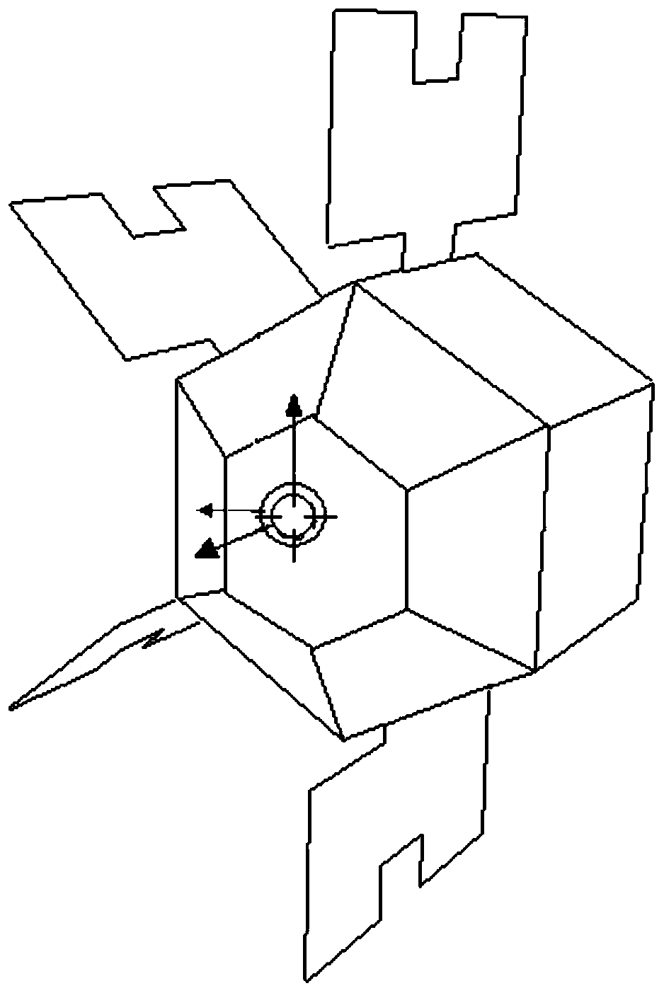
[0108] right Figure 4 The model shown is scanned and sampled by an analog sensor. During the sampling process, the model performs variable speed movement around the rotation axis; the analog sensor generates a sequence of point clouds, and the effect of the point cloud is as follows: Figure 4 Shown...


PUM


Abstract

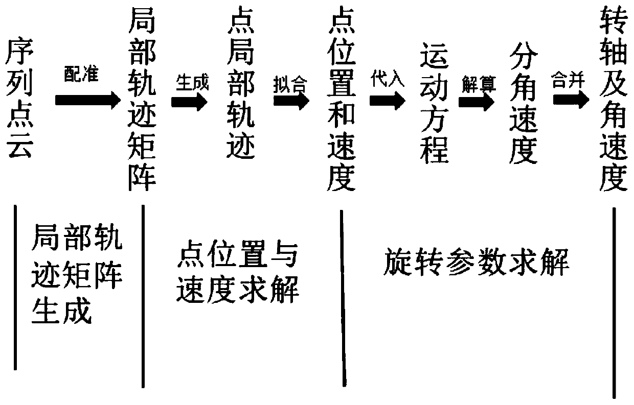
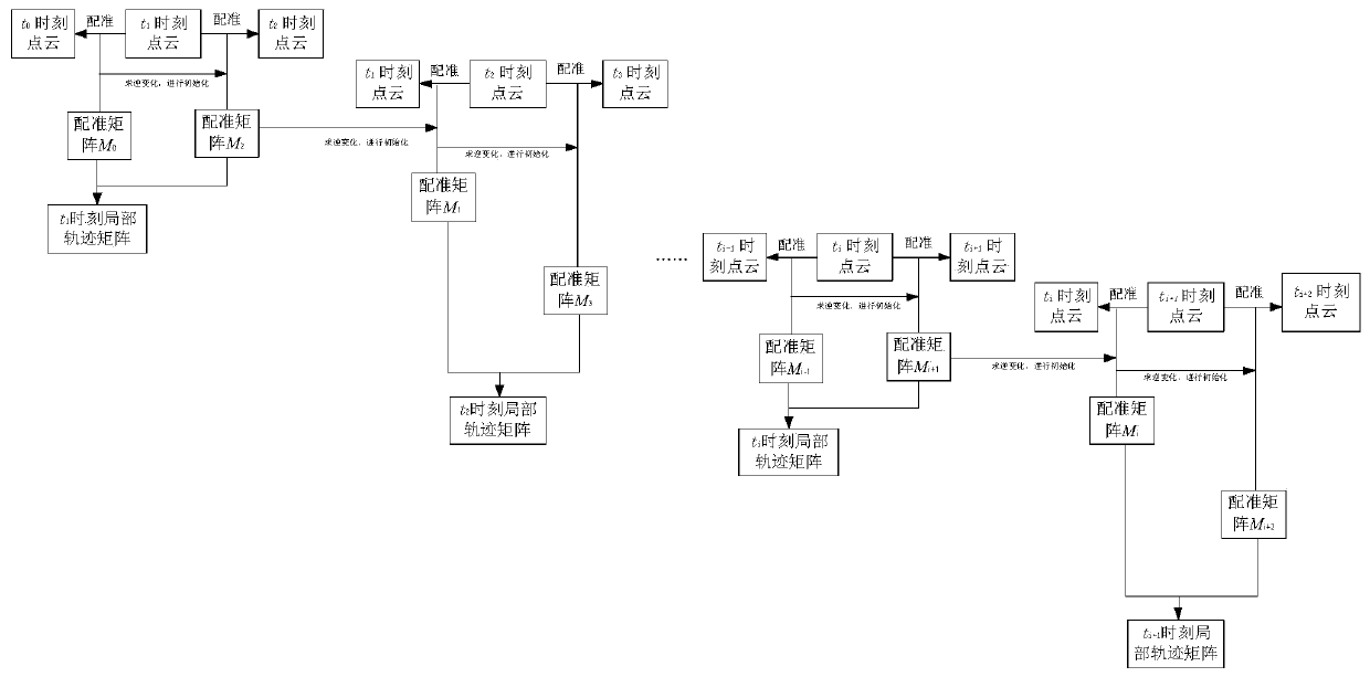
The invention provides a rotating shaft direction and rotating angular velocity resolving method for a moving rotating object, which comprises the following steps of: firstly, registering an adjacentpoint cloud at the moment by using a nearest point iteration point cloud registration algorithm, and constructing a local track matrix by using a registration matrix; secondly, point position information is obtained according to a local track matrix, point track fitting is carried out, the speed of a certain point at a certain moment is solved, and finally an equation is established according to the rigid body rotation physical process to carry out rotation parameter resolving; according to the method, dependence on feature points is avoided, and the motion condition of a target at a certain moment is described by using a local track matrix; good robustness is achieved on point cloud local loss caused by self-shielding of the target, and errors caused by incomplete feature point tracks inthe sequence point cloud are avoided; the method can effectively solve the rotating shaft and the rotating angular velocity, especially when the angular velocity of the rotating object is variable motion, the solving result can better track the change of the set angular velocity, the solving precision is higher, and the solving advantage is more obvious.

Description

technical field [0001] The invention belongs to the field of calculating rotation parameters of moving objects and scanning point clouds, and in particular relates to a method for calculating the rotation axis direction and rotation angular velocity of a moving rotating object. Background technique [0002] In the field of spaceflight, the solution of the motion parameters of space non-cooperative targets is the premise of target tracking, detection and on-orbit approach, so the research on the motion parameters of space non-cooperative targets is a very important research field. A commonly used technical method is to use laser or camera sensors to observe and scan non-cooperative targets to obtain a sequence of 3D point clouds of non-cooperative targets. In general, the motion parameters of non-cooperative targets, such as motion speed, rotation axis direction and rotation angular velocity, can be obtained according to the sequence point cloud. [0003] At present, there a...

Claims


Application Information

Patent Timeline
IPC IPC(8): G06T7/20G06T7/292
CPCG06T7/20G06T2207/10028G06T7/292
Inventor 赵玺邹建华李家钊敖毅波徐笑昂
Owner XI AN JIAOTONG UNIV
Learn More