
Winding machine of transformer

A technology for transformers and winding machines, which is applied in the manufacture of inductors/transformers/magnets, coils, electrical components, etc. It can solve the problems of large size of winding machines, unreasonable design of gluing device, cumbersome adjustment and operation of wire inlet device, etc.

Pending Publication Date: 2019-08-09
淮安市品优德科技有限公司
View PDF0 Cites 2 Cited by
  • Summary
  • Abstract
  • Description
  • Claims
  • Application Information

AI Technical Summary

Problems solved by technology

[0003] Different types of transformers have different types of enameled wires in their windings. Although the current winding machines on the market can be used for windings of different types of enameled wires, the adjustment of the wire inlet devices for different types of enameled wires is cumbersome; in addition, currently on the market The winding machine mechanism for transformer winding has many stations, and each step requires a special station, resulting in a larger size and higher cost of the winding machine. The industry is in urgent need of a machine with fewer stations, a simple mechanism but a The equipment that can complete the winding of the transformer; moreover, the design of the gluing device of the current winding machine on the market is not reasonable enough. Not only does it need to stop frequently to add tape, but also the effect of gluing the tape needs to be improved, especially at the junction of the tape and the cutting tape. There will be problems. Once the treatment is not good, the tape on the tape roll or the tape originally wound on the transformer frame will be pulled out due to stress when the tape is cut.

Method used


Image

  • Winding machine of transformer
  • Winding machine of transformer
  • Winding machine of transformer

Examples


Embodiment Construction

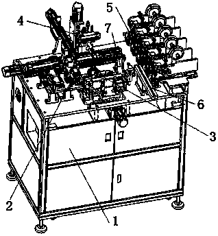
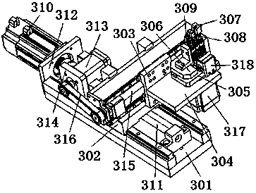
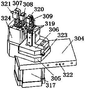
[0079] combine Figure 1~Figure 12 It can be seen that a winding machine for a transformer in the present invention includes a chassis 1, and the top of the chassis 1 is respectively provided with a threading sleeve device 2, a wire tube transmission turnover device 3, a transformer turnover feeding device 4, a glue application device 5, a transformer The feeding device 6 and the blanking track 7, the wire pipe transfer turnover device 3 is movably connected between the threading casing device 2 and the transformer turnover feeding device 4, and the transformer turnover feeding device 4 is movably connected to the transformer feeding device 6 , Between the line pipe transfer turnover device 3, the glue applicator 5 and the blanking track 7.

[0080] The wire tube conveying turnover device 3 includes a horizontal rail frame A301 fixed on the top of the cabinet 1, and the horizontal rail frame A301 is provided with a longitudinal rail frame A302 that moves horizontally along the...


PUM


Abstract

The invention discloses a winding machine of a transformer. The winding machine comprises a cabinet, the top portion of the cabinet is provided with a threading sleeve device, a wire pipe conveying turnover device, a transformer turnover feeding device, a rubberizing device, a transformer feeding device and a blanking rail. The wire pipe conveying turnover device is movably connected between the threading sleeve device and the transformer turnover feeding device, and the transformer turnover feeding device is movably connected among the transformer feeding device, the wire pipe conveying turnover device, the rubberizing device and the blanking rail. According to the structure, the winding machine of the transformer achieves the full automation of the tube threading, winding, rubberizing and wire arrangement of the transformer.

Description

technical field [0001] The invention relates to the technical field of automatic winding equipment for transformers, in particular to a winding machine for transformers. Background technique [0002] In other electronic products such as transformers and motors, there are core components formed by winding enameled wires. During the production and preparation of these core components, it is often necessary to put Teflon tube sleeves on the beginning and end of the enameled wires. In order to increase its excellent tin climbing and pressure resistance, however, because these components are in the production process, the enameled wire is automatically wound by a winding machine. [0003] Different types of transformers have different types of enameled wires in their windings. Although the current winding machines on the market can be used for windings of different types of enameled wires, the adjustment of the wire inlet devices for different types of enameled wires is cumbersom...

Claims


Application Information

Patent Timeline
IPC IPC(8): H01F41/06H01F41/12H01F41/10H01F41/061
CPCH01F41/06H01F41/125H01F41/127H01F41/10H01F41/061
Inventor 许大华许健
Owner 淮安市品优德科技有限公司
Learn More