Check patentability & draft patents in minutes with Patsnap Eureka AI!

Mechanism for raising and lowering vehicle window glass

A lifting mechanism and window glass technology, applied in vehicle parts, manual mechanisms, windshields, etc., can solve the problems of window glass tilting, encouragement, etc., and achieve the effect of preventing window glass from tilting.

Active Publication Date: 2019-08-09
AISIN CORP +1
View PDF5 Cites 0 Cited by
  • Summary
  • Abstract
  • Description
  • Claims
  • Application Information

AI Technical Summary

Problems solved by technology

Therefore, there is a problem that when the load plate is lowered to the bottom dead center by the power transmission unit (wire) and the window glass is fully opened, the load plate rotates relative to the guide rail, causing the window glass to tilt.
In addition, the sliding direction of the load plate with respect to the guide rail is not a complete vertical direction (vertical direction), but is often an inclined vertical direction (vertical direction) including components in the front and rear directions of the vehicle, which also contributes to the above-mentioned problems.

Method used


Image

  • Mechanism for raising and lowering vehicle window glass
  • Mechanism for raising and lowering vehicle window glass
  • Mechanism for raising and lowering vehicle window glass

Examples


Embodiment Construction

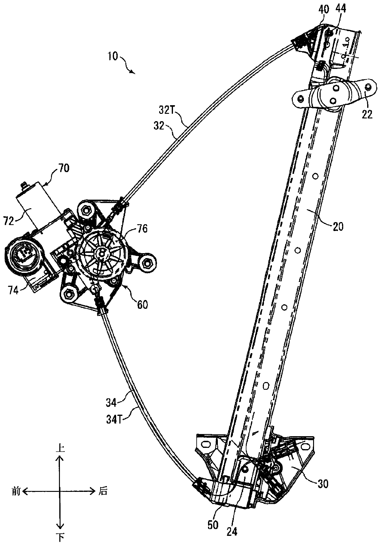
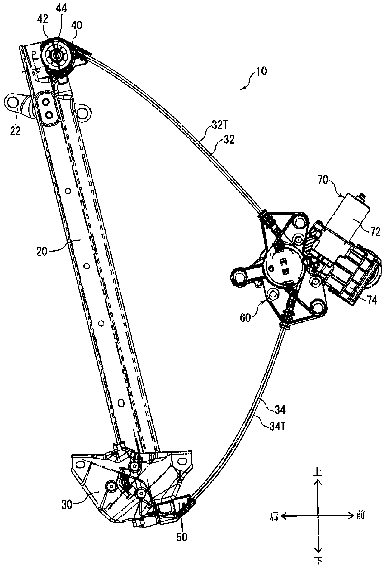
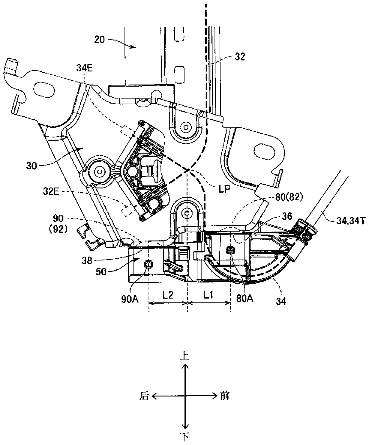
[0020] refer to Figure 1 to Figure 6 A vehicle window lift mechanism (window regulator) 10 according to the present embodiment will be described. The directions in the following description are based on the arrow-line directions described in the drawings. exist Figure 1 ~ Figure 2 and Figure 3 ~ Figure 6 Among them, the structure of the vehicle window lift mechanism 10 (in particular, the structure of the carrier plate 30 and the lower guide member 50) is different, but this is only for the convenience of drawing. Figure 1 ~ Figure 2 It is an orientation of a conceptual diagram showing the basic structure of the window glass lift mechanism 10 for a vehicle, and the characteristic parts of the window glass lift mechanism 10 for a vehicle according to this embodiment (the structure of the support plate 30 and the lower guide member 50, and the two The support structure near the bottom dead center (falling end) of the component) is expressed in Figure 3 ~ Figure 6 .

[...


PUM


Abstract

Provided is a mechanism for raising and lowering vehicle window glass that can prevent a window glass from tilting by a carrier plate rotating even when the carrier plate is lowered to bottom dead center and the window glass is fully opened. A carrier plate (30) has a force application unit (LP) to receive the force from a wire (32, 34) to move in the lowering direction. Two stopper members (80, 90) are provided separated in the front-to-rear direction of the vehicle in a positional relationship so as to straddle the force application unit (LP) of the carrier plate (30).

Description

technical field [0001] The invention relates to a window glass lifting mechanism for a vehicle. Background technique [0002] Patent Document 1 discloses a window regulator device for opening and closing a window glass. The vehicle window regulator device has a guide rail, a bearing plate, and a limiting component. The guide rail is fixed on the door. The carrier plate has a rail fitting portion fitted to the rail, a window glass fixing portion, and a coupling portion for coupling a power transmission unit (wire) for transmitting power generated in the driving portion, and is slidably attached. on the guide rail. The limiting component limits the sliding position of the bearing plate. A shock absorber made of an elastic member is assembled on one side of the carrier plate and the stopper. On the other side of the carrier plate and the stopper member, a collision surface with the shock absorber is formed. The collision surface has a shape that presses the load plate tow...

Claims


Application Information

Patent Timeline
Patent Type & Authority Applications(China)
IPC IPC(8): E05F11/48B60J1/17E05F11/38
CPCE05F11/486E05Y2201/212E05Y2201/64E05Y2201/654E05Y2201/684E05Y2800/678E05Y2900/55E05F15/689B60J1/17
Inventor 梶本祐太堤直毅山崎隆太
Owner AISIN CORP
Features
  • R&D
  • Intellectual Property
  • Life Sciences
  • Materials
  • Tech Scout
  • Unparalleled Data Quality
  • Higher Quality Content
  • 60% Fewer Hallucinations
Learn More