Pot casting mold assembly and pot casting method

A technology for die-casting molds and pots, which is applied in the fields of pot casting and pot casting mold components, can solve the problems of difficult discharge of air bubbles, leakage of liquid at the edge of the pot, and achieve the effects of improving quality and yield and being convenient to use.

Pending Publication Date: 2019-08-13
YANTAI ZHONGDE ENVIRONMENTAL PROTECTION EQUIPTECH
View PDF0 Cites 3 Cited by
  • Summary
  • Abstract
  • Description
  • Claims
  • Application Information

AI Technical Summary

Problems solved by technology

[0003] The invention aims at the problem that the air bubbles are not easily discharged and the liquid leak

Method used


Image

  • Pot casting mold assembly and pot casting method
  • Pot casting mold assembly and pot casting method
  • Pot casting mold assembly and pot casting method

Examples


Embodiment 1

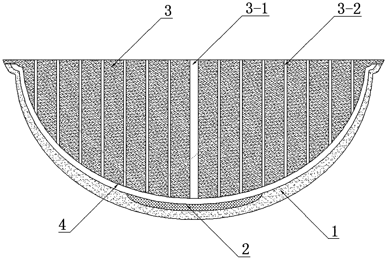
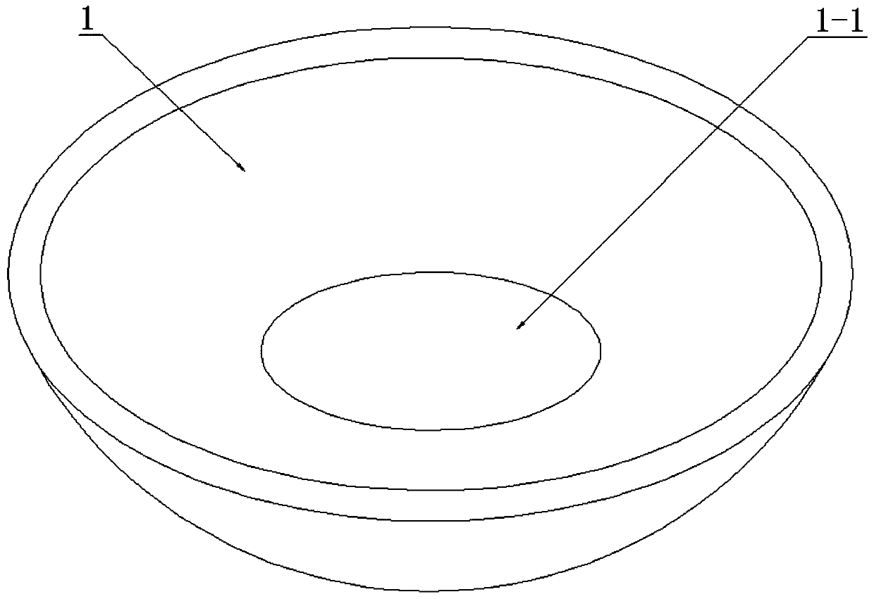
[0019] Such as figure 1 , 2 As shown in and 4, a pot casting mold assembly includes a bottom mold 1, a fin mold 2 and an upper mold 3, the bottom mold 1 and the upper mold 3 are mud molds or metal molds, and the fin mold 2 is a film-coated sand mold , the bottom mold 1 is a semi-ellipsoidal cavity, the bottom center of the bottom mold 1 cavity is provided with a slot 1-1, the fin mold 2 can be movably embedded in the slot 1-1, the upper surface of the fin mold 2 and the bottom The surface of the mold 1 cavity is bonded, the upper surface of the finned mold 2 is provided with fin patterns 2-1, the upper mold 3 is semi-ellipsoidal, and the center is provided with a casting channel 3-1 perpendicular to its upper surface, and the upper mold 3 There are air-dispersing micropores 3-2 parallel to the sprue 3-1 evenly distributed inside, and an annular flange is provided on the edge of the upper mold 3, and the annular flange is pressed against the edge of the bottom mold 1, and the ...

Embodiment 2

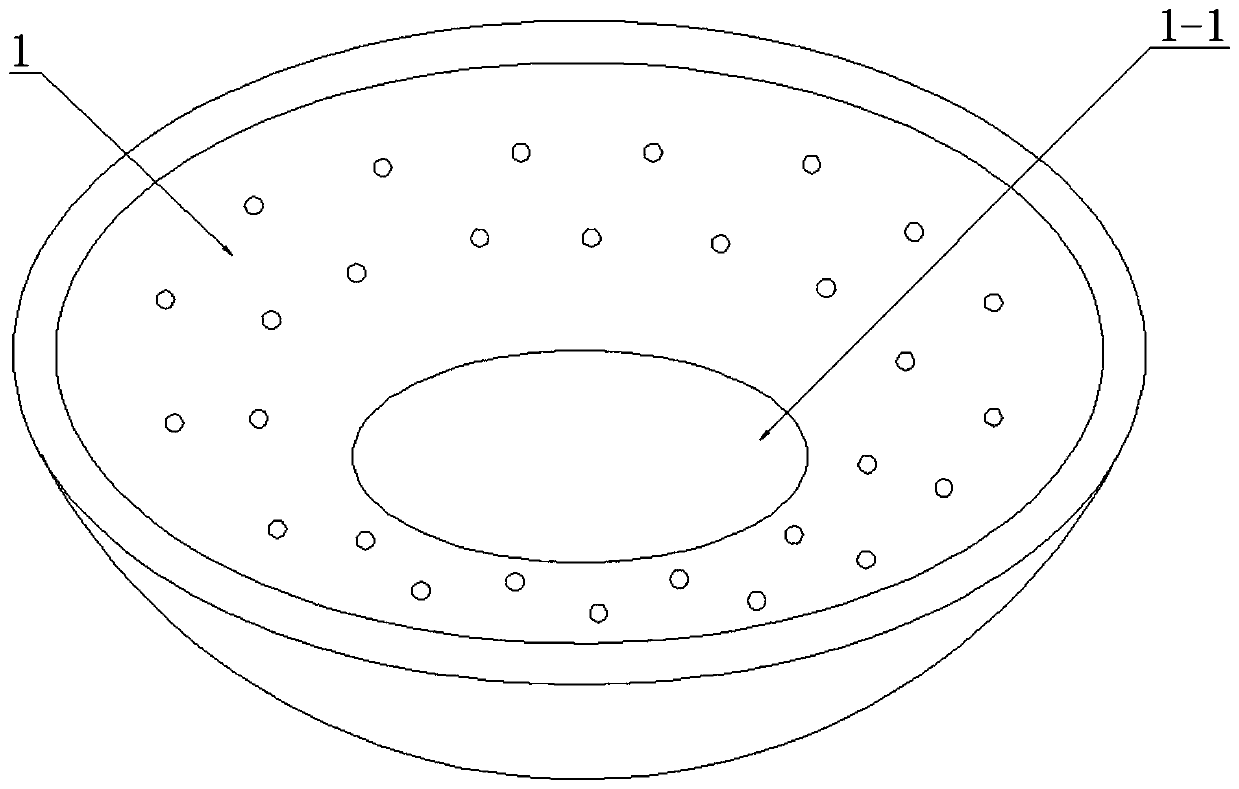
[0021] Such as figure 1 , 3 As shown in and 4, a pot casting mold assembly includes a bottom mold 1, a fin mold 2 and an upper mold 3, the bottom mold 1 and the upper mold 3 are mud molds or metal molds, and the fin mold 2 is a film-coated sand mold , the bottom mold 1 is a semi-ellipsoidal cavity, evenly distributed with air holes penetrating the bottom mold 1, the bottom center of the bottom mold 1 cavity is provided with a slot 1-1, and the fin mold 2 can be movably embedded in the slot 1-1 Inside, the upper surface of the fin mold 2 is attached to the surface of the cavity of the bottom mold 1, the upper surface of the fin mold 2 is provided with fin patterns 2-1, the upper mold 3 is semi-ellipsoidal, and the center is provided with The casting path 3-1 of the upper mold 3 is evenly distributed with air-dispersing micropores 3-2 parallel to the casting path 3-1, and the edge of the upper mold 3 is provided with an annular flange, which is connected to the edge of the bott...

Embodiment 3

[0023] Such as figure 2 , 4 As shown in and 5, a pot die-casting mold assembly includes a bottom mold 1, a fin mold 2 and an upper mold 3, the bottom mold 1 is a semi-ellipsoidal cavity, and the bottom center of the bottom mold 1 cavity is provided with a slot 1 -1, the fin mold 2 can be movably embedded in the slot 1-1, the upper surface of the fin mold 2 is attached to the cavity surface of the bottom mold 1, and the upper surface of the fin mold 2 is provided with fin patterns 2-1; The mold 3 is in the shape of a semi-ellipsoid, and there are evenly distributed air-dispersing micropores 3-2 perpendicular to the upper surface of the upper mold 3 and passing through the upper mold 3, and a connecting piece 3-3 is arranged at the center of the upper surface of the upper mold 3; the bottom mold 1 and the upper mold 3 are mud molds, and the fin mold 2 is a coated sand mold.

[0024] The invention also discloses a pot casting method. In addition to the above-mentioned pot die-...


PUM


Abstract

The invention discloses a pot casting mold assembly. The pot casting mold assembly comprises a bottom mold, a fin mold and an upper mold. The bottom mold is a semi-ellipsoidal cavity. An embedding groove is formed in the center of the bottom of the bottom mold cavity. The fin mold is movably embedded in the embedding groove. The upper surface of the fin mold is bonded to the surface of the bottommold cavity. The upper surface of the fin mold is provided with fin patterns. The upper mold is semi-ellipsoidal, and a casting path perpendicular to the upper surface of the upper mold is formed in the center of the upper mold. Exhaust micropores parallel to the casting path are uniformly distributed in the upper mold. The edge of the upper mold is provided with an annular flange. The annular flange is press-fitted with the edge of the bottom mold. A casting cavity is formed among the bottom mold, the fin mold and the upper mold. The casting path and the exhaust micropores communicate with the casting cavity. According to the pot casting mold assembly, when an iron pot is cast, a pot opening faces upwards, the pot bottom faces downwards, casting liquid is gathered at the bottom, the liquid level gradually rises as the casting liquid increases, the liquid level discontinuity phenomenon is avoided, and the casting liquid does not produce a large number of bubbles; and since the bottom mold is intact, connection of different casting molds is avoided, and the casting liquid does not overflow.

Description

technical field [0001] The invention relates to kitchen utensil preparation, in particular to a pot casting mold assembly and a pot casting method. Background technique [0002] Pots are indispensable kitchen utensils in people's daily life. According to the source of preparation materials, they are divided into iron pots, aluminum pots, casserole pots, stainless steel pots, etc. Among them, the iron pot has stable chemical properties and is not easy to cause chemical reactions. When cooking, a small amount of iron will be dissolved, which can be absorbed and utilized by the human body, which is beneficial to health. Iron pan has a long history and scope of use, and is one of the representatives of traditional kitchen utensils. In order to improve the heat storage and uniform heat performance of the iron pot, it is also a common configuration to install fins at the bottom of the iron pot. The heating area of ​​the bottom of the pot is larger than that of traditional pots, a...

Claims


Application Information

Patent Timeline
IPC IPC(8): B22D17/22
CPCB22D17/22B22D17/2272
Inventor 赵颂
Owner YANTAI ZHONGDE ENVIRONMENTAL PROTECTION EQUIPTECH
Why Eureka
Try Eureka